20.10.2023
A high-voltage generator from an ignition coil, cooler and mosfet - easy and affordable. How to make a bedini charger from a computer cooler DIY generator from a cooler diagram
If you have an old computer cooler at home, you can build an excellent wind turbine that will produce electricity. A mini wind generator is a great thing, especially for areas with frequent and strong winds. We will learn about the features and technology of its production further.
How to make a mini wind generator with your own hands
Work on a mini wind generator should begin by making drawings of the future wind turbine. In addition, you should prepare materials in the form of:
- thick plastic bottle;
- an old cooling cooler or fan, the power of the generator itself directly depends on its size and power;
- low-current wire in the amount of 5-8 meters;
- wooden beam, the cross-section and dimensions of which are determined individually;
- two steel pipes that fit into one another;
- diodes;
- epoxy-based glue and super adhesive composition;
- fastening elements in the form of tightening ties;
- old CD.

First of all, you need to start by finding a suitable cooling mechanism. We suggest using a cooler from an old computer. Initially, the cooler is disassembled, its propeller part is located on electric motor. Most often, it is fixed on a retaining ring; it is located under a rubber seal. After removing the O-ring, remove the blades on the fan.
Next comes the process of soldering the cables that ensure the operation of the generator set. There are two wire connections on the copper fan coils, these are the connectors on the coils. One of the sections is distinguished by the presence of a connected copper wire, and the second has two wires. Two wires are connected to the legs of one wire by soldering.
At the next stage of creating a small wind generator, a rectifier is created. The main function of this device is to convert AC to permanent. For these purposes, you will need four diodes; they are cut so that one pair from the black mark remains with a 10 cm segment. The long end of the diode is bent to form a U-shaped connection. All diodes are connected to each other by soldering. To test a wind generator, connect diodes to it, if the LED works, then the wind generator is functioning correctly. The outer plastic part of the cooler is removed; use a knife to smooth out any irregularities.

Next comes the manufacturing process of the wind generator blade. To make blades, use an old bottle, such as a shampoo bottle. The top and bottom parts of the bottle are cut off. The product will be cylindrical in shape; it needs to be cut lengthwise. Pre-make a drawing in the form of blades, according to it, cut out the blades for the wind generator from the bottle. Please note that the end part of the blades must be cut at an angle of one hundred and twenty degrees. Next comes the process of fixing the blades to the cooler.
At the next stage, the windmill tail is manufactured. To fix the motor, a beam made of wood is used. Its rotation is carried out using steel tubes. To make a shank, use a waste disk. The wooden block is equipped through hole, its diameter should be slightly larger than the diameter of the steel pipe. If the tube is not installed tightly, fix it with epoxy-based glue. At the end of the block, a cut is made for mounting the disk. The place where the motor is connected to the bar must also be treated with adhesive. It is also recommended to cover wires and soldering with glue to prevent corrosion.
Next comes the process by which the support is made. To construct it, use two tubes. One of them is fixed on a wooden block, and the second is set in relation to rotation. You can use bearings to connect them, and use fluoroplastic to improve sliding.

Do-it-yourself mini wind generator from a motor
We offer an option for making a wind generator from a motor from an old printer. This model It has average performance and works even in the slightest wind. To operate the wind generator, you will also need a battery; the maximum power of the device is 100 mA.
The main part of the windmill is a motor from a non-working inkjet printer. The printer must first be disassembled and the motor removed from it.
A transistor is used to lock the blades. It must be drilled in relation to the size of the shaft being installed. Next, all parts are fixed using an epoxy-based adhesive. In addition, this composition protects critical parts of the device from moisture and bad weather.
Using a piece of plastic pipe, about 12 cm in diameter, cut out the blades for the windmill. A cutting machine is used for these purposes. The optimal width of the part is 90 mm, the holes are made with a special device, and then the shaft is installed on the generator motor using screw connections.

A pipe with a diameter of 55 mm is used as the basis for the manufacture of a windmill. To make the tail, use plywood. The motor is installed inside the pipe. Next, the rectifier is constructed. Because the motor does not produce a large amount of electricity when there is little wind. Thus, it is possible to apply a doubling scheme switched on in series.
The circuit is installed in a plastic bag and installed inside the pipe along with the rectifier. Next, the motor is fixed using a wire. In addition, all holes are sealed with a silicone gun. One hole is used for water drainage, and the second for evaporation of condensate masses.
A bolt and wire are used to secure the tail of the wind generator. In this way, the installation will be securely fixed. Monitor the rigidity of the resulting joints.
In order to build a mast for installing a windmill, use beams connected to each other using self-tapping screws. Fix the windmill on the mast and install it in a previously designated place. With this installation you can charge your mobile phone or provide lighting.

Making a mini wind generator with your own hands
Before you start working on a wind generator, you need to determine the amount of wind in your climate region. Gray-green - windless zones imply the use exclusively of sail-type wind generators. If necessary, provision DC, a device in the form of a booster is added to them. This device acts as a rectifier and also stabilizes the voltage. You will also need a charger, a high-power battery, and a converter. The cost of manufacturing this installation is prohibitively high and is not always justified.
In areas with low winds, indicated in yellow, it is possible to manufacture a low-speed wind generator. These devices have good performance.
For windy regions, any wind turbines are suitable. Most often, vertical type devices are used - paddle boats or sailboats.

In order to perform calculations to determine the power of a wind turbine, it is necessary to take into account factors such as:
- constant wind speed in a particular region;
- air is a continuous medium, therefore the power of the wind generator depends on the quality and performance of the rotor;
- air currents have kinetic energy.

We propose to consider the features of sailing wind generators. These devices are made of wear-resistant material that perfectly withstand winds. If you decide to make such an installation yourself, then you must first of all carry out a series of calculations related to these devices.
As a material for making a wind generator, you can use various pieces of iron that are lying around your home. The most expensive element is the battery. Its power determines the size of the installation and its productivity.
It is quite easy to make a homemade axial type wind generator at home. Work should begin with the mast. For its manufacture, pipes are most often used; they must be different in diameter. A welding machine is used to connect the pipes to each other. The mast is installed on a concreted platform. At the same time, several meters of it are deepened into the ground to obtain a stable structure. Two magnets need to be glued onto individual parts of the installation. For stronger fixation, they are additionally filled with epoxy resin.
Next comes the process of making the mold and plywood. For these purposes, coils connected by a phase are used. The stator manufacturing process looks like this: wax paper is installed on a previously cut square of plywood. Next comes the installation of plywood, on which holes are pre-cut for mounting the stator. Next comes the process of installing the fiberglass circle and installing the coils.

After this, the finished stator is removed from the previously prepared mold. A duralumin pipe is used to make the screw. The screw is made with a diameter of one meter. Use an electric jigsaw to cut out the blades. In the central part of the installation, equip a hole with which the screw will be fixed to the generator.
The wind generator has a tail element offset relative to the axis. When there are strong gusts of wind, pressure occurs on the surface of the wind generator and it moves to the side. This scheme allows you to protect your device from strong winds. This wind generator model allows you to generate enough energy to provide street lighting for your home. Making a wind generator is not difficult; the main condition for obtaining a high-quality device is to compare the strength of the wind in your region with its power.

Do-it-yourself mini wind generator manufacturing technology
Manufacturing a wind generator requires a minimum supply of tools and materials. We offer an option for constructing a mini wind generator for a summer residence. This device is able to provide a small house with a minimum number of electrical appliances - electricity.
To make such a wind generator, you will first need a disk on which magnets are mounted. Next comes the process of winding copper coils, which are filled with resin. To carry out rotation, the generator is installed on a previously provided base.
These wind generators have good performance and quality work. The ratio of magnet to poles is two to three if the wind generator has two phases, for single-phase device A ratio of one to three is sufficient. All poles are related to each other depending on the coil options used.

The power of a wind generator is determined primarily by the size of the magnets used in its construction. As a mast for the generator, it is sufficient to use a steel pipe or log. It is not necessary to use new batteries; any devices of suitable power will do.
It is possible to manufacture several wind generators at once, and each of them will perform certain functions - one provides the home with light, the second is responsible for the operation of the TV, and the third is responsible for night lighting.
In this article I will tell you how to make an engine - a Bedini generator from a computer cooler. This device model is one of the lowest power, but at the same time it is very convenient to use, cheap and easy to manufacture. It is very convenient to conduct experiments with the model. It takes up very little space and is easy to maintain. I will tell you the best, in my opinion, way of making it.
You will need: Transistor 2N3055 TO-3; Diode 1 N 4001 and 1 N 4007; Resistor 47 Ohm - 100 Ohm (I recommend 51 Ohm, 1W -2W); 1kΩ trim resistor (I recommend R-17N1-B1K, L15KC or 3296W-1-102LF potentiometer 1K(SP5-2VB)); computer cooler (I took JF0925S1H, fan 12V, 92x92x25mm), but in general it doesn’t matter what kind of stickers there will be on the cooler; terminals, crocodiles. You can buy all this at a radio store, electrician, or take it out of radio devices; I bought it at the Voltmaster store. I really liked the store, their prices are an order of magnitude lower than others. You also need a neon light bulb NE - 2. Take it out of the starter for the fluorescent lamp, a radiator (you can take a piece of aluminum, you can take it out of some unnecessary radio equipment), a piece of plywood or organic glass 16.5mm * 15.5mm and other small fittings( single-core and stranded wires, bolts, nuts).

Here is the diagram to assemble:

Here is a visual diagram:


Now attach the transistor to the heatsink and the heatsink to the base.


The next step is to prepare the cooler. Remove the sticker, then the rubber plug from reverse side. Using a small screwdriver or tweezers, remove the cotter pin (circlip). Remove the blades.

You will see 4 coils attached to the chip with three legs. Grab the core of the coils with pliers and insert a small screwdriver into the space for the blade axle. Holding everything firmly by the core, hit the screwdriver with a hammer. The microcircuit with coils must separate from the entire structure.

Unsolder the coils from the microcircuit. The chip has 3 pins, you must insert a cutoff pin as the fourth pin. There are 2 wires soldered to one of the legs, unsolder one and solder it to the new leg so that there is one wire going to each leg.

Place the coil assembly back onto the axle, solder 4 different colored wires and lead them out.

The question is trivial. First, we recommend determining where to install your homemade fan. Two types of engines dominate in technology: commutator (historically the first), asynchronous (invented by Nikola Tesla). The first ones make a lot of noise, switching sections causes a spark, the brushes rub, causing noise. An asynchronous motor with a squirrel-cage rotor is quieter and generates less interference. You will find the start-up protection relay in the refrigerator. By adding a couple of phrases of humorous phrases, we will return the seriousness of the site. How to make a fan with your own hands without scaring your family. Let's try to answer.
Aspects of designing a homemade fan
The design of the fan is so simple that there is no point in telling or describing the insides. What to consider when designing? Remember the growl of a cyclonic vacuum cleaner, the volume is above 70 dB. Inside brushed motor. Often deprived of the ability to regulate speed. Decide, is a similar sound pressure level acceptable at the installation site of a homemade fan? Having chosen the second, we will concentrate on asynchronous motors, simple models do not require a starting winding. The power is low, the secondary EMF is induced by the stator field.
The drum of an asynchronous motor with a squirrel-cage rotor is cut with copper conductors along the generatrix, at an angle to the axis. The direction of the slope determines the direction of rotation of the engine rotor. Copper conductors are not insulated from the drum material, the conductivity of the Olympic metal exceeds the surrounding material (silumin), the potential difference between adjacent conductors is small. Current flows through copper. There is no contact between the stator and rotor, the spark has nowhere to come from (the wire is covered with varnish insulation).
The noise of an asynchronous motor is determined by two factors:
- Alignment of stator and rotor.
- Bearing quality.
By correctly setting up and servicing an asynchronous motor, you can achieve almost complete noiselessness. We recommend considering whether sound pressure level is important. The case concerns a duct fan - it is allowed to use a commutator motor, the requirements will be determined by the location of the section.
The duct fan is placed inside the air duct section and mounted, breaking the duct. The section is removed for maintenance.
Noise loses its dominant role. The sound wave, passing through the air duct, attenuates. Particularly fast is the part of the spectrum that has inconsistent dimensions relative to the width/length of the path section. Read more textbooks on acoustic lines. The brushed motor can be used in a basement, garage, or unoccupied areas. The neighbors of the cooperative will hear, but will rather be too lazy to pay attention.
What is good about a commutator engine, what are we fighting for the right to use. Three disadvantages of asynchronous:

At the initial moment asynchronous motor does not develop high torque, a number of special design measures are taken. It doesn't matter for the fan. Majority household models equipped with asynchronous motors. In production, the number of phases is increased to three.
Finding a motor for a fan
One YouTube video suggested using a 3 volt DC motor from a hardware store. Tops a USB cord, works by rotating the laser disc blade. Useful invention? If you're tired of the extra port, this will help you survive the heat. It’s easier to take a processor cooler and power it from the system unit. The yellow wire goes to 12 volts (red to 5). The black pair is earth. You can assemble it from an old computer. Citizens of the Russian Federation are simply too lazy to invent, so we throw interesting equipment into a landfill.

Asynchronous fan motors operate without a starting capacitor... The peculiarity of fan motors is that they come directly with a winding. A couple of tips to help you get an engine:

Make a fan impeller
The question of what to make a fan from has not been resolved; the authors kept silent about the impeller. First things first, the refrigerator! The compressor is blown by an impeller. When you get the motor out, remove it. It will come in handy. Regarding washing machine, launch the drum onto an aircraft propeller. A plastic tank can be used to make a body. Heat the bend areas with a hair dryer.
Inspect the blender and equip it with an unnecessary laser disk shaped like an impeller. You can make a fan yourself using available materials. You don't need a lot of power, and there's no point in trying too hard to fine-tune the details. We believe that readers know how to make a fan with their own hands.
Eternal CPU cooler fan
We decided to please our readers by telling you how to make a fan. This is not the first review, I had to dig around to find something worthwhile. The idea of creating an eternal fan that spins forever looks great. User mail.ru posted a design that looks attractive. Let's take a closer look, while thinking about how to make a fan that runs forever.
You know, of course, system units work quietly ( modern models). The slightest noise means: the cooler's axis is out of whack, or it's time to lubricate the old fan. They work for hours, days add up to weeks, the system unit will last for years. It became possible thanks to well-thought-out technology. Think about it, noise depends on the magnitude of the friction force. Mechanical energy becomes thermal and acoustic due to the presence of roughness. CPU coolers rotate easily, just blow on them.

The author of the video - we apologize for the lack of a name, we justify: the video is in English - suggests assembling an eternal fan from an accessory. The fitting accuracy of the parts is high, the blade rotates easily. Costs are reduced to a minimum. The author of the video posted by the deirones channel noted: the processor fan is powered by direct current. I climbed inside and found four coils, equally spaced around the circumference, with their axes directed towards the center of the device.
There are no commutators inside, which means a paradoxical fact: the field of the coils is constant.
If the induction motor of a typical fan is powered by 220 volts alternating voltage, which creates a rotating magnetic field, in our case the picture is constant. You could say: inside the rotor sets in motion a commutator that creates the desired distribution. This is not true, and is confirmed by the author’s further train of thought and the result of experience. A Western innovator decides to replace the coil with a permanent magnet. Indeed, there is no alternating field - why electric current?
The author demonstratively cuts off the power cord and places neodymium magnets ( hard drive) frame perimeter. Each is on the continuation of the coil axis. The work is completed, the blades begin to rotate vigorously. We believe that a principle is simply used that is hushed up in orthodox literature. Trade secret of the patent holder.

The initial movement of the blade is obtained by random air fluctuations. Reminiscent of a magnetron, the vibrations are caused by the natural chaotic movement of elementary particles. The question arose as to what determines the direction of rotation. The design is absolutely symmetrical. We decided to look into it and express our observations:

Agree, it’s more convenient than messing up USB ports and constantly wasting batteries. The eternal fan operates from an arbitrary position and is devoid of wires. We believe that the strength of the magnets plays a decisive role. The simple rule no longer works: more is better. A golden mean is emerging. When the blades spin from a random air flow, overcoming a field of neodymium pieces. Weak magnets are probably powerless to maintain stable rotation. The field strength must be exactly that created by the coils under the influence of +5 or +12 volts.
Correctly create an eternal fan
We discussed how to make a fan, measure the direction, force magnetic field coils Enjoy special devices. A magnetometer, Teslameter, is formed by a magnetic induction converter, a measuring module. When fields interact, the resulting pattern is called coupling. The converter generates EMF. The size is determined by the measured strength of the magnetic field. Like two fingers! Costs 10,000 rubles.
The magnets will be located at a considerable distance from the axis. The coils are much closer. You need to know how the picture changes with distance. According to Coulomb's law, the force decreases in inverse proportion to the square of the distance, which is true for single charges of arbitrary sign. Separate magnetic poles have not yet been found in nature (it is not possible to create them); the cube of distance is included in the law. Let's say the distance to the coil from the axis is 1 cm, the diagonal perimeter is 10. This means that neodymium should be 10 x 10 x 10 = 1000 times stronger than a small coil.
Nobody obliges to place neodymium magnets around the fan perimeter on diagonals. The poles lie crosswise. Adjust the force of influence over a wide range. By placing neodymium magnets in the center of the sides of the fan frame, we significantly increase the field strength. Let's do the calculation. Let's say the hypotenuse of a triangle with a side of 10 cm is a diagonal. The distance to the center of the square will be equal to 10 / √2 = 7 cm. You see, the ratio drops from 1000, reaching 7 x 7 x 7 = 343. We are desperate to find strong neodymium magnets to create an eternal fan.
Let's measure the strength! A compass is suitable (there are custom designs that you can assemble yourself, for example, http://polyus.clan.su/index/indikatory_magnitnogo_polja_svoimi_rukami/0-52). One coil should be connected to the power supply. Then find the position, the arrow brought up will deviate by about 45 degrees (if you don’t like it, take any other azimuth). Then start experimenting with neodymium. Place the piece at different distances, ensuring that the arrow deflection coincides with that obtained when using the processor fan coil. Surely the distance is not equal to the diagonal, half the side, the neodymium will have to be broken and cut.
By sawing one edge along the length, we carefully break the parts on a nail, obtaining the required field strength to create an eternal fan. We assume that the induction is distributed proportionally to the volume. Today we explained clearly how to make a fan with your own hands!
Power supply
Anyone who wants to make a fan with their own hands sees 3 problems: getting a motor, power supply, and making a propeller. The parts must fit together. Three problems solved, you can start making a fan with your own hands. Today there are an abundance of switching power supplies at home. Think about it, it started in the 90s. Game consoles, mobile phones, other equipment. Equipment breaks down, switching power supplies remain. The voltage is sometimes non-standard; most motors operate on any voltage. The revolutions will simply change according to the voltage. If you have broken household appliances lying around at home, immediately make a fan yourself.

Homemade fan power supplies
People are constantly trying to make a special fan with their own hands. One issue is often beyond the scope of discussion: the power source. The design of the fan itself is so obvious that there is no point in going into more detail. So, it’s clear that there are an unimaginable number of batteries today. Will they be able to work for a long time? The answer is no. As a last resort, take the “crown”; in Soviet times it was considered a reliable source of energy. The power supply is bad, the power will gradually drop, the speed will decrease, and it will irritate people. Stability without additional effort is important. There is no small 12 volt battery - get ready: let's start looking for how to make a power source for a homemade fan.
The first thing that comes to mind is to screw up the computer. It is known that miniature devices are powered by a USB port. Gadgets are recharging. The USB port is a source of inexhaustible energy. The voltage is low, you will need a low voltage DC motor. We believe you can find it at home or buy it at a hardware store. How much port power will be: according to old standards, 2–3 W. Another thing is to find a host device with an updated version of the interface (2014 was considered a rarity). The developers promised to deliver 50 W (it’s hard to believe even more). True, there will be more wires, the rated voltages will increase. We remind you that according to tradition, power is supplied to the red (+), black (-) wires. White, green - signal.
It's clear, high power It’s difficult to expect - even if the port supports, the motor will not pull. It is recommended to look for a higher voltage. The motor must be supplied with higher voltage. For example, it is recommended to use a processor cooler. The supply voltage is less than the required 12 volts, the rotation speed will simply decrease. Beware of exceeding it - the motor may burn out.
We are looking for energy, the question is easier to solve than for 3 volts:

12 volt power supply for a homemade do-it-yourself fan
We suggest not collecting pulse block food, do it yourself with your own hands. Let us remember that the former are distinguished by small-sized transformers. Therefore, the power supply will be relatively large in size. Will consist of the following parts:
- Step-down transformer. We will not name the number of turns in advance, the voltage is unknown, rectifying it with diodes, we get 12 volts. Of course, you can experiment, like the YouTube video about homemade radios, grab the reader and look for a ready-made solution.
- The bridge is full-wave; by adding three to one diode, we increase the efficiency. Radio components are not very expensive.
- The backbone of the power supply is ready so that the homemade fan can serve for a long time, let’s straighten out the network ripples. After the bridge, we will turn on the low-pass filter and redraw the circuit from the Internet.

The output is a constant voltage with an amplitude of 12 volts. Be careful not to mix up the terminals. Where the “plus” comes out and where the “minus” comes out can be understood by studying the diagram. Below is a drawing of the bridge, look and read the explanations. In radio electronics, the direction of current is indicated opposite to the true one. Charges flow, according to popular belief, in the direction from plus to minus (towards electrons). Reading the diagram, you will see: the emitter of the diode, transistor, marked with an arrow, looks incorrectly. In the direction of movement of positive charges. Each one has marks and is indicated on the diagram by a huge triangle arrow. Consequently, we always find out “plus”, guided by the graphic symbols given in the drawing.
The figure shows: the plus will be on the right, transmitted according to the diode arrow to the lower output terminal. The minus will go up. With alternating voltage (roughly speaking), plus and minus will alternate from left to right, the name of the rectifier will become clear - full-wave. Works on the positive part of the voltage and the negative. Take power, low-frequency diodes. Solid size, power dissipation is relatively high. You can calculate using a simple formula taken from a physics course. We multiply the resistance of the open p-n junction (we leaf through the reference book) by the current consumed by the motor, taking the margin at least 2 times. The motor housing contains an inscription indicating the power, which can be divided by the voltage of 12 volts, simply multiplied by 2 - 3, and taken a diode with equivalent power dissipation (see reference book).

Now let's calculate the transformer... We went here http://radiolodka.ru/programmy/radiolyubitelskie/kalkulyatory-radiolyubitelya/, chose the Trans50 program, we will master it. Please note that there is software available that allows you to calculate filter parameters. Do you regret that you decided to make a fan yourself? They offer to choose one of 5 windings. Steel is involved everywhere. You can make do, the losses will be great. The steel forms a magnetic circuit, the energy goes to the secondary winding. It's better to find an old rusty transformer. Times are bad; in the hungry 90s, landfills were littered with plates of scrapped windings. There were no problems with winding the transformers.
It's time to understand what voltage is required for the correct operation of the circuit. A term borrowed from electronics will help: AC voltage. Voltage at the active resistance creating a thermal effect equal to the constant voltage of the effective amplitude. To obtain the required voltage on the secondary winding, you need to divide 12 volts by 0.707 (one divided by the square root of 2). The authors received 17 volts. The engineering calculation has an error of 30%, let's take a small margin (part of the amplitude up to 1 volt will be lost on the diodes).
As for the secondary winding current (required for calculation), type something like “cooler power” into a search engine. Let's do it together with the readers. Smart articles write: the current consumption of the cooler is indicated on the case. Once you have the required parameter, we’ll plug it into the calculator. The author took the voltage of the secondary winding to be 19 volts. The voltage drop across the p-n junctions of powerful silicon diodes is 0.5 - 0.7 volts. Therefore, an appropriate reserve is needed. Smart heads searched and concluded that the processor cooler does not consume more than 5 W, therefore, the current is 5 divided by 12 = 0.417 A. We substitute the numbers into the downloaded calculator, and for the strip core we get the transformer design parameters:
- The cross-section of the magnetic core for winding is 25 x 32 mm.
- Window in the magnetic circuit 25 x 40 mm.
- The magnetic core is finished with a frame for winding wire with a thickness of 1 mm and a cross-section of 27 x 34 mm.
- The wire is wound along the larger side of the window, leaving a margin of 1 mm from the edges, for a total of 38 mm.
The primary winding is formed by 1032 turns with a diameter of 0.43 mm. The approximate length of the wire is 142 meters, the total resistance is 17.15 Ohms. The secondary winding consists of 105 turns of a copper core with varnish insulation with a diameter of 0.6 mm (length 16.5 meters, resistance 1 Ohm). Now readers understand: the question of what to make a fan from begins to be decided by the core...
How effective are the proposed technical solutions? Fans are known to Ancient Egypt. Evidenced by a Michael Jackson video recommending “Remember the time.” The plot was hardly prepared without the consultation of archaeologists and historians. We would like to report that in Mexico, most ladies use fans. The Spaniards know how to deal with the heat; the country lies on the equator. Think about it...
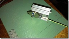
Hello everyone! There are many schemes on the Internet high voltage generators differing in power, assembly complexity, price and availability of components. This homemade product is assembled from almost waste parts; anyone can assemble it. This generator was assembled, let’s say, for informational purposes and all kinds of experiments with high voltage electricity. The approximate maximum of this generator is 20 kilovolts. Since this generator does not use mains voltage as a power source, this is an additional plus from a safety point of view.

The photo shows all the necessary parts to assemble a high-voltage generator.
For assembly you will need:
Ignition coil from VAZ
Cooler with hall sensor
"N" channel mosfet
100 Ohm and 10 kOhm resistors
Connecting insulated wires
Soldering iron
Terminal block (optional)
Heatsink for mosfet
Several screws
Plywood base for fastening parts

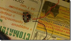
If anyone is interested, I’ll try to tell you more. A computer cooling cooler or similar 12 volt is used as a pulse generator, but with one condition - it must have a built-in hall sensor. It is the hall sensor that will generate pulses for the high-voltage transformer, which, in this case, is the ignition coil from the car. Choosing a suitable fan is very simple; as a rule, it has three inputs.

The photo shows the presence of three conclusions. The standard color is red pin plus power, black – common (ground) and yellow – output from the hall sensor. When power is supplied to the fan at the output (yellow wire), we receive pulses, the frequency of which depends on the speed of the electric motor of a given cooler and the higher the voltage, the higher the frequency of the pulses. The voltage should be increased within reasonable limits - approximately 12-15 volts, so as not to burn the cooler and the entire circuit. The resulting pulse signal must be applied to the ignition coil, but it must be amplified.

As power key used "N" channel field effect transistor(mosfet) IRFS640A others with similar parameters are suitable, or approximately for a current of 5-10 amperes and a voltage of 50 volts for reliability. Mosfets are present in almost all modern electronic circuits, be it a computer motherboard or starting circuit energy-saving lamp, which means there will be no problems finding a suitable one.

The ignition coil from VAZ “classic” B117-A cars has three terminals. The central one is a high-voltage output, “B+” is positive 12 volts, and the general “K” is probably not marked.
Initially, the circuit consisted of three components: a cooler, a mosfet and a coil, but after a short time of operation it broke down, as either the mosfet or the hall sensor failed. Output – setting 100 Ohm resistors for limiting starting current from the hall sensor to the gate, and a 10 kOhm pull-up resistor to shut off the mosfet in the absence of a pulse.

When assembling the circuit, the transistor should be installed on a radiator, preferably using thermal paste, since the heating during operation is significant.

I used the connector from the cooler as a terminal block to connect the mosfet. As a result, there is no need to solder the transistor; to connect or replace it, it is enough to connect the block to the terminals of the transistor.

The fan was secured on top of the radiator using two self-tapping screws. As a result, it turned out that the cooler plays a dual role - as a pulse generator and as additional cooling.
The Bedini motor is charger for battery. Which in turn feeds the motor itself. Such a peculiar one" perpetual motion machine"This design differs in many ways from the standard options that are found on the Internet. The basis of the Bedini motor was a cooler from a computer power supply.As you know, such motors cannot operate directly from a DC source, so a special driver is built inside, which powers the motor windings. The essence of the Bedini motor is getting higher voltage on a removable winding, which has no connection with the main winding. On this winding it is formed alternating voltage, the rating of which is much higher than the motor supply voltage.

The resulting voltage is rectified and charges the battery, which in turn powers the motor. Today you can find on the Internet various modifications this engine, but the essence is the same. By principle, the Bedini motor is a kind of voltage converter. Standard versions of the Bedini motor usually have a separate circuit for powering the motor. You can often find diagrams on one bipolar transistor, in our version everything is simplified as much as possible.

Many coolers have an excitation winding; it is designed to start the engine. The winding is easy to determine if you disassemble the cooler. Typically, the excitation winding has low resistance and is easily determined by continuity; by eye, the wire of this winding differs in the color of the varnish.

We unsolder the ends of this winding from the main board and bring it out, it will serve as a pick-up winding. This winding is capable of delivering up to 20 volts if the engine is powered from 14 volts DC voltage. Of course, this voltage is low, but the point of the article is only a demonstration of the device.

The main alteration is completed here, then you need to prepare a small stand on which to install the motor.

The current in the removable winding depends on many factors - power, revolutions per minute, wire thickness, etc... In this motor, the current in the second winding is no more than 100 mA. And for a snack interesting video for the manufacture of a device based on a transistor converter:
According to Bedini, the whole “secret” is to correctly alternate battery discharges with its own charges with pulses of “radiant energy” from the generator. And this is where the quality of the received pulses and the possible range of their regulation may simply not provide the conditions under which the battery will actually begin to charge beyond unity. In this case, both the cycle frequencies and the ratio of the durations of their parts (charge - discharge) must be specially selected for each type and type of battery. AKA KASYAN
Discuss the article MOTOR BEDINI

