02.08.2023
Controlling a brushless motor using back EMF signals - understanding the process. Typical control circuits for electric drives with DC and AC motors Control circuit for a DC brushed motor
DC motors are rarely found in households. But they are always present in all children's toys powered by batteries that walk, run, ride, fly, etc. Direct current motors (DC motors) are installed in cars: in fans and various drives. They are almost always used in electric vehicles and less frequently in manufacturing.
Advantages of DPT compared to asynchronous motors:
- Well adjustable.
- Excellent starting properties.
- Rotation speeds can be more than 3000 rpm.
Disadvantages of DBT:
- Low reliability.
- Difficulty of manufacturing.
- High cost.
- High maintenance and repair costs.
Operating principle of a DC motor
The engine design is similar synchronous motors AC. I won’t repeat myself, if you don’t know, then look in this one of ours.
Any modern electric motor works based on Faraday's law of magnetic induction and the "Left Hand Rule". If an electric current is connected to the lower part of the armature winding in one direction, and to the upper part in the opposite direction, it will begin to rotate. According to the left-hand rule, conductors laid in the armature slots will be pushed out magnetic field windings of the DPT housing or stator.
The lower part will push to the right, and the top one to the left, so the anchor will begin to rotate until the parts of the anchor change places. To create continuous rotation, it is necessary to constantly reverse the polarity of the armature winding. This is what the commutator does, which, when rotating, switches the armature windings. Voltage from the current source is supplied to the collector using a pair of pressing graphite brushes.
Schematic diagrams of a DC motor
If AC motors are quite simple connect, then with DPT everything is more complicated. You need to know the brand of the motor, and then find out about its connection circuit on the Internet.
More often for medium and powerful engines DC there are separate terminals in the terminal box from the armature and from the field winding (OB). As a rule, the full power supply voltage is supplied to the armature, and the field winding -adjustable current rheostat or alternating voltage. The speed of the DC motor will depend on the magnitude of the OB current. The higher it is, the faster the rotation speed.
Depending on how the armature and OB are connected, electric motors come with independent excitation from a separate current source and with self-excitation, which can be parallel, series and mixed.
Used in production motors with independent excitation, which is connected to a power source separate from the armature.  There is no electrical connection between the field and armature windings.
Connection diagram with parallel excitation in essence it is similar to a circuit with independent excitation of the OB. The only difference is that there is no need to use a separate power source.  Motors, when switched on according to both of these schemes, have the same rigid characteristics, therefore they are used in machine tools, fans, etc.
Series-wound motors used when high starting current and soft characteristic are required. They are used on trams, trolleybuses and electric locomotives. According to this scheme, the field and armature windings are connected to each other in series.  When voltage is applied, the currents in both windings will be the same. The main disadvantage is that when the load on the shaft decreases to less than 25% of the nominal value, there is a sharp increase in the rotation speed, reaching values dangerous for the DPT. Therefore, for trouble-free operation, a constant load on the shaft is necessary.
Sometimes used DBT with mixed arousal, in which one OB winding is connected in series to the armature circuit, and the other in parallel.  Rarely occurs in life.
Reversing DC Motors
To change the direction of rotation DPT with series excitation requires changing the direction of the current in the OB or armature winding. In practice, this is done by changing the polarity: we swap the plus and minus positions. If you change the polarity in the excitation and armature circuits at the same time, then the direction of rotation will not change. The reverse is done in a similar way for motors running on alternating current.
Reversing DPT with parallel or mixed excitation It is better to do this by changing the direction of the electric current in the armature winding. When the excitation winding breaks, the EMF reaches dangerous values and a breakdown of the wire insulation is possible.
Regulating the speed of DC motors
DPT with sequential excitation The easiest way to regulate is by variable resistance in the armature circuit. It can only be adjusted to reduce the speed in a ratio of 2:1 or 3:1. In this case, large losses occur in the control rheostat (R reg). This method is used in cranes and electric trolleys that have frequent interruptions in operation.  In other cases, the speed is adjusted upward from the nominal value using a rheostat in the field winding circuit, as shown in the right figure.
DPT with parallel excitation You can also regulate the speed of revolutions downwards using resistance in the armature circuit, but not more than 50 percent of the nominal value. Again, the resistance will heat up due to losses of electrical energy in it.
Increase the speed by a maximum of 4 times allows a rheostat in the OB circuit. The simplest and most common method of adjusting the rotation speed.
In practice, in modern electric motors these control methods are rarely used due to their shortcomings and limited control range. Various are used electronic circuits management.
Similar materials.
The simplest method for controlling the rotation speed of a DC motor is based on the use pulse width modulation(PWM or PWM). The essence of this method is that the supply voltage is supplied to the motor in the form of pulses. In this case, the pulse repetition rate remains constant, but their duration can vary.
The PWM signal is characterized by such a parameter as the duty cycle or duty cycle. This is the reciprocal of the duty cycle and is equal to the ratio of the pulse duration to its period.
D = (t/T) * 100%
The figures below show PWM signals with different duty cycles.
With this control method, the motor rotation speed will be proportional to the duty cycle of the PWM signal.
Simple DC Motor Control Circuit
The simplest DC motor control circuit consists of a field-effect transistor, the gate of which is supplied with a PWM signal. The transistor in this circuit acts as an electronic switch that switches one of the motor terminals to ground. The transistor opens at the moment of the pulse duration.

How will the engine behave when turned on like this? If the frequency of the PWM signal is low (several Hz), the motor will turn jerkily. This will be especially noticeable with a small duty cycle of the PWM signal.
At a frequency of hundreds of Hz, the motor will rotate continuously and its rotation speed will change in proportion to the duty cycle. Roughly speaking, the engine will “perceive” the average value of the energy supplied to it.
Circuit for generating a PWM signal
There are many circuits for generating a PWM signal. One of the simplest is a circuit based on a 555 timer. It requires a minimum of components, requires no setup and can be assembled in one hour.
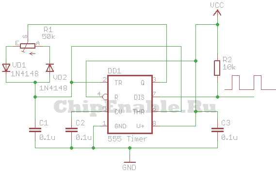
The VCC circuit supply voltage can be in the range of 5 - 16 Volts. Almost any diodes can be used as diodes VD1 - VD3.
If you are interested in understanding how this circuit works, you need to refer to the block diagram of the 555 timer. The timer consists of a voltage divider, two comparators, a flip-flop, an open collector switch and an output buffer.

The power supply (VCC) and reset pins are connected to the power supply plus, say +5 V, and the ground pin (GND) to the minus. The open collector of the transistor (DISCH pin) is connected to the power supply positive through a resistor and the PWM signal is removed from it. The CONT pin is not used; a capacitor is connected to it. The THRES and TRIG comparator pins are combined and connected to an RC circuit consisting of a variable resistor, two diodes and a capacitor. The middle pin of the variable resistor is connected to the OUT pin. The extreme terminals of the resistor are connected through diodes to a capacitor, which is connected to the ground with the second terminal. Thanks to this inclusion of diodes, the capacitor is charged through one part of the variable resistor and discharged through the other.
At the moment the power is turned on, the OUT pin is at a low logical level, then the THRES and TRIG pins, thanks to the VD2 diode, will also be at a low level. The upper comparator will switch the output to zero, and the lower one to one. The output of the trigger will be set to zero (because it has an inverter at the output), the transistor switch will close, and the OUT pin will be set to a high level (because it has an inverter at the input). Next, capacitor C3 will begin to charge through diode VD1. When it charges to a certain level, the lower comparator will switch to zero, and then the upper comparator will switch the output to one. The trigger output will be set to a unity level, the transistor switch will open, and the OUT pin will be set to a low level. Capacitor C3 will begin to discharge through diode VD2 until it is completely discharged and the comparators switch the trigger to another state. The cycle will then repeat.
The approximate frequency of the PWM signal generated by this circuit can be calculated using the following formula:
F = 1.44/(R1*C1), [Hz]
where R1 is in ohms, C1 is in farads.
With the values indicated in the diagram above, the frequency of the PWM signal will be equal to:
F = 1.44/(50000*0.0000001) = 288 Hz.
PWM DC motor speed controller
Let's combine the two circuits presented above, and we get a simple DC motor speed controller circuit, which can be used to control the engine speed of a toy, robot, micro drill, etc.
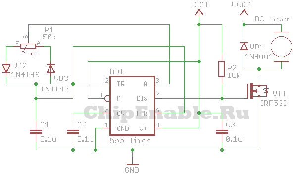
VT1 is an n-type field-effect transistor capable of withstanding maximum current motor at a given voltage and shaft load. VCC1 is from 5 to 16 V, VCC2 is greater than or equal to VCC1.
Instead of a field effect transistor, you can use bipolar n-p-n transistor, Darlington transistor, opto-relay of appropriate power.
Currently, DC motors are widely used in various industries. DC motors are used where smooth and precise control of speed and torque over a wide range is required. In this article I will talk about creating a control unit for a DC motor that would allow changing the speed of the motor shaft and stabilize the speed at a certain level, regardless of the load on the motor shaft.
The development is based on the operating principle of a servo drive with a single-circuit control system.
The control unit consists of the following components:
- SIFU (Pulse-Phase Control System)
- Regulator
- Protection
Schematic diagram drive is shown below.
Larger
Let's take a closer look at the diagram.
So, SIFU (Pulse-Phase Control System) - converts the sinusoidal network voltage into a series of rectangular pulses going to the control electrodes of power thyristors. When turning on the control unit alternating voltage 14-16V is supplied to bridge rectifier D1, where it is converted into a pulsating voltage, which serves not only to power the circuit, but also to synchronize the operation of the drive. Diode D2 prevents the smoothing of pulses by capacitor C1. Next, the pulses arrive at the “zero detector” - DA1.1, assembled on one op-amp of the LM324 chip, operating in comparator mode. While there is no pulse, the voltages at the direct and inverse inputs are approximately equal and the comparator is in a balanced state. When the phase passes through “0”, pulses appear at the inverse input of the comparator DA1.1, which plays the role of a “zero detector”, switching the comparator, as a result of which rectangular synchronizing pulses are generated at the output of DA1.1, the repetition period of which is strictly tied to the phase transition through “0” "
Below are oscillograms that explain the operating principle. 
From top to bottom: KT1, KT2, KT3.
The circuit was simulated in Multisim 11. Here is the project file. You can download, run and see how this node works.
Next, the clock pulses are sent to an integrator with a transistor switch (C4, Q1), where a sawtooth voltage is generated. At the moment the phase passes through “0,” the clock pulse opens transistor Q1, which discharges capacitor C4. After the pulse decays, the transistor closes and the capacitor is charged until the next clock pulse arrives, resulting in Q1 on the collector (oscillator KT4). a linearly increasing sawtooth voltage is formed, stabilized by a stable current generator made on field-effect transistor T1. The amplitude of the “saw” equal to 9V is set by trimming resistor RP1. The “saw” voltage is supplied to the direct input of the comparator DA1.2.
The reference voltage is supplied to the inverse input of the comparator DA1.2 and at the moment when the sawtooth voltage exceeds the voltage at the inverse input of the comparator, the comparator switches and a pulse is formed at the output of the comparator (oscillation KT4). The pulse is differentiated through the chain R14, C6 and goes to the base of transistor Q2. The transistor opens and opening pulses of the power thyristors are formed on the pulse transformer Tr1. By increasing (decreasing) the reference voltage, the duty cycle of the pulses in CT5 changes.
Here are the oscillograms. 
But we will not see any impulses in KT5 until we press the “Start” button - S1. When the button is not pressed, the +12V supply voltage through the normally closed contacts S1 along the chain R12, D3 is supplied to the inverse input DA1.2 and is equal to about 11V. Since this voltage exceeds the “saw” voltage of 9V, the comparator is locked and control pulses for opening the thyristors are not generated. To prevent accidents and failure of the engine, if the operator does not set the speed controller to “0,” the circuit provides an acceleration unit C5, R13, which serves for smooth acceleration of the engine. In the “Start” mode, the circuit works as follows: when you press the “Start” button, the normally closed contacts open and capacitor C5 along the chain - “ground”, R13, - C5 begins to smoothly charge and the voltage on the negative plate of the capacitor smoothly tends to zero. At the same time, the voltage at the inverting input DA1.2 smoothly increases to a value determined by the reference voltage, and the comparator begins to generate control pulses for the power thyristors. The charging time is determined by the ratings C5, R13. If during engine operation it is necessary to change its speed in order to avoid sudden surges in speed, the circuit provides an “acceleration-braking” unit R21, C8, R22. When the reference voltage increases (decreases), capacitor C8 is smoothly charged (discharged), which prevents a sharp “surge” of voltage at the inverse input of the amplifier and, as a result, prevents a sharp increase in engine speed.
Now let's look at the principle of operation speed controller.
The regulator is designed to maintain constant engine speed in the control zone. The regulator is a differential amplifier with the summation of two voltages: the reference voltage and the feedback voltage. The reference voltage is set by resistor RP1 and is supplied through filter R20, C8, R21, which simultaneously performs the functions of an “acceleration-braking” unit, and is supplied to the inverse input of the op-amp regulator DA1.3. As the reference voltage at the output of op-amp DA1.3 increases, the output voltage decreases linearly.
The output voltage of the regulator is supplied to the inverse input of the comparator SIFU DA1.2 where, summed with sawtooth voltage pulses, it is converted into a series of rectangular pulses going to the control electrodes of the thyristors. As the reference voltage increases (decreases), the output voltage at the output of the power unit also increases (decreases).
This graph shows the dependence of engine speed on the reference voltage. 
Engine speed values are given as an example.
The voltage divider R22, R23 connected to the direct input of the DA1.3 regulator serves to prevent engine failure when the feedback is broken (if the feedback is broken, the engine goes into overdrive).
When the drive is turned on, the tachogenerator begins to generate voltage, proportional to revolutions engine. This voltage is supplied to the input of a precision detector DA1.4, DA2.1 assembled using a full-wave circuit. The voltage taken from the output of the precision detector DA1.4, DA2.1 is supplied through filter C10, R30, R33 to the scaling feedback amplifier DA2.2. The amplifier is used to adjust the feedback voltage coming from the tachogenerator. Voltage from the output of op-amp DA2.2. is supplied both to the input of the regulator DA1.3 and to the protection circuit DA2.3.
Resistor RP1 sets the engine speed. When the engine is running without load, the voltage at the output of the scaling amplifier is lower than the voltage at pin 6 of op-amp DA1.3. ≈ +5v, so the drive works as a regulator. As the load on the motor shaft increases, the voltage received from the tachogenerator decreases and, as a consequence, the voltage from the output of the scaling amplifier decreases.
When this voltage is less than the voltage at pin 5 of op-amp DA1.3, the drive enters the current stabilization zone. A decrease in the voltage at the non-inverting input of op-amp DA1.3 leads to a decrease in the voltage at its output, and since it operates on the inverting amplifier DA1.2, this leads to a larger opening angle of the thyristors and, consequently, to an increase in the voltage at the motor armature.
PROTECTION CIRCUIT
Overspeed protection is designed to protect the engine from an accident if the set engine speed is suddenly exceeded. The circuit is assembled using op-amp DA2.3, connected according to the comparator circuit. The reference voltage from the divider R36, R37, RP3 is supplied to the inverse input of the comparator. Resistor RP3 sets the protection threshold. The voltage from the output of the scaling amplifier DA2.2 is supplied to the direct input of the protection comparator DA2.3. When the engine speed exceeds the rated speed, the voltage at the direct input of the comparator exceeds the threshold of the protection setting determined by RP3 - the comparator switches. Due to the presence of positive feedback in the circuit, R38 causes the comparator to “click,” and the presence of diode VD12 prevents the comparator from resetting. When the protection is triggered, the voltage from the output of the protection comparator (≈ +11v) through the VD14 diode is supplied to the inverse input 13 of DA1.2 SIFU, and since the protection voltage exceeds the “saw” voltage (= 9v), the issuance of control pulses to the control units is instantly prohibited thyristor electrodes. The voltage from the output of the protection comparator DA2.3 opens the transistor VT4, which leads to the operation of relay P1.1 and the lighting of the LED VL1 signaling an emergency situation. You can remove the protection only by completely de-energizing the drive, and after pausing for 5 - 10 seconds, turning it on again.
Power part of the control unit.
The power section diagram is shown below 
Transformer Tr1 is designed to power the control unit circuit. The controlled rectifier is assembled using a half-bridge symmetrical circuit and contains two power diodes D1, D2
and two power thyristors T1, T2, and a protective diode D3. The field winding is powered by its own separate transformer and rectifier.
If the engine does not have a tachogenerator, then feedback to control speed can be performed as follows:
1. Use a current transformer connected to the power circuit of the controlled rectifier 
If a current transformer is used, then place jumper P1 on the control unit diagram
to position 1-3, this is necessary because as the load increases, the armature current will increase, therefore the voltage removed from the current transformer will also increase, so the feedback voltage must be applied to the inverting
output of the DA1.3 chip. You can also install a standard current shunt, but only in the motor armature circuit, after the rectifier, and remove the feedback signal from it.
2. Use an armature voltage sensor. The diagram is shown below. 
The armature voltage sensor is a filter-divider and is connected directly to the armature terminals of the electric motor. The drive is configured as follows. Resistors “Task” and “Scaling Uoc” are set to the middle position. Resistor R5 of the armature voltage sensor is placed in the lower “ground” position. We turn on the drive and set the voltage at the motor armature to approximately 110 volts. By controlling the voltage at the motor armature, we begin to rotate resistor R5. At a certain point of regulation, the voltage on the armature will begin to decrease, this indicates that the feedback has begun to work.
Now let's move on to the design and adjustment of the control unit.
The control unit was made on a printed circuit board (PCB file) 

The board is connected by MGTF wire to the connector for easy dismantling during repairs.
Settings
During setup, the power part was assembled using a wall-mounted installation, and a regular incandescent lamp was used as a load. 
We begin the setup by checking the supply voltages and the supply voltage at operational amplifiers DA1, DA2. It is advisable to install microcircuits in sockets. Then we monitor the oscillograms at control points KT1, KT2, KT3 (oscillograms at these points are given at the beginning of the description of the SIFU). Now, we place the oscilloscope at the control point KT4. There should be sawtooth pulses, as in the osillogram above (the “Start” button should be open at this moment). Using the trimming resistor RP1, it is necessary to set the saw swing to 9 volts; this is a very important point, since the further operation of the circuit depends on it. Since the spread in the parameters of field-effect transistors can be quite significant, perhaps the adjustment range of RP1 may not be enough, then by selecting the value of resistor R10, achieve the desired range. At the control point KT3, the pulse duration should be 1.5 - 1.8ms; if not, then select resistor R4 (towards a decrease) to achieve the required duration.
By rotating the RR1 regulator at control point KT5, check the change in the duty cycle of the pulses from maximum to their complete disappearance when the RR1 slider is in the lower position. In this case, the brightness of the light bulb connected to the power unit should change.
Next, we connect the control unit to the engine and tachogenerator. We set it with the RR1 regulator
armature voltage is about 40-50 volts. Resistor RP3 should be set to the middle position. By controlling the voltage on the motor armature, we begin to rotate resistor RP3. At a certain point of regulation, the voltage on the armature will begin to decrease, this indicates that the feedback has begun to work. For those who want to experiment: to increase the rigidity of the drive, you can also increase the resistance R24, thereby increasing the gain of the regulator, or increase the resistor R32.
If motor armature current feedback is used.
For this, as mentioned above, you need a current transformer included in the power circuit
controlled rectifier. The current transformer calibration diagram is given below. By selecting a resistor, obtain an alternating voltage of ≈ 2 ÷ 2.5v at the transformer output. Load power RN1 must match the engine power. 
Attention! Do not turn on the current transformer without a load resistor.
We connect the current transformer to the feedback circuit P1 and P2. While setting up the “Regulator”, it is advisable to unsolder the D12 diode to prevent false triggering of the protection.
Oscillograms at control points KT8, KT9, KT10 should be as in the figure below. 
Further settings are the same as in the case of using a tachogenerator.
If motor armature voltage feedback is used.
As noted above, you can apply armature voltage feedback; for this, an armature voltage sensor is assembled. The control unit is configured as follows. Resistors “Task” and “Scaling Uoc” are set to the middle position. Resistor R5 of the armature voltage sensor is placed in the lower “ground” position. We turn on the drive and set the voltage at the motor armature to approximately 110 volts. By controlling the voltage at the motor armature, we begin to rotate resistor R5. At a certain point of regulation, the voltage on the armature will begin to decrease, this indicates that the feedback has begun to work.
This control unit was manufactured for a boring machine. Here is a photo of this monster 

On this machine, the electric machine amplifier, which controlled the DC motor for moving the table, failed.
Here's an electric machine amplifier. 
This control unit was made instead.
Here is a photo of the DC motor itself. 
The control unit was assembled on an insulating base, where all the main elements are located. 
Power diodes and thyristors are installed on heat sinks. A panel with connectors was also made, where signals from the control points of the circuit were output. This was done for ease of setup and repair directly on the machine.
Here is the mounted control unit in the power cabinet of the machine 


A small control panel was installed on the other side of the power cabinet. 
It contains:
-toggle switch for turning on the unit
-operating mode toggle switch. Since for the installation movements of the machine table, precise control and stabilization of revolutions are not needed, the feedback circuit is bypassed during this time.
- knobs for adjusting the number of revolutions. Two variable resistors were supplied, one for rough adjustment, the second - multi-turn - for precise setting of the required speed during rough and fine boring of the part.
For those interested, below is a video of the machine in operation. First, the boring of a hole in a 20mm thick steel plate is shown. Then it is shown at what frequency the machine table feed screw rotates. At this speed, the part is fed to the cutter, and this speed of rotation of the feed screw is provided by the DC motor, for which, in fact, all this was done.
The control unit performed well, there were no failures or accidents.
DC motors are widely used due to their low cost and high efficiency. Most often, such motors are used in start/stop mode and do not require any control gear for their connection, except for an ordinary switch. However, it is often necessary to adjust the rotation speed, shaft torque or position of the mechanism driven by the engine. In such cases, microprocessor control units for DC motors are used. The simplest engine speed controller is a power supply with a variable output voltage or a PWM regulator (this is what is sold on Aliexpress). These are simple and inexpensive solutions, but such a regulator does not have feedback - the engine speed with such a regulator depends on the load on the shaft. To solve this problem, rotation speed feedback is introduced into the regulators. The simplest option for obtaining information about the engine rotation speed is to install a tachogenerator or pulse sensor on its shaft. Such solutions solve the problem of stabilizing the engine rotation speed, but complicate the design of the product and increase its cost. Modern microprocessor technologies make it possible to use the electric motor itself as a tachogenerator (almost all electric machines are reversible), measuring the EMF generated by the engine at the moment of short-term disconnection of the supply voltage from it. This solution seems to be optimal in terms of price/quality ratio.
The second important parameter for regulating commutator motors is the torque on the motor shaft. In most cases, torque limitation is required to prevent damage to the engine or mechanism itself. A mode of stabilization of the engine output torque is often necessary, for example, to control the electric drive of a scooter or to adjust the tension force of a machine for restringing tennis rackets. The instantaneous value of the motor armature current is most often used as the output torque signal.
And the third control parameter is the position or coordinate of the mechanism driven by the DC motor. Controlling speed, torque and position allows you to create full-fledged servos based on commutator motors. The position feedback signal can be obtained from an analog potentiometric sensor or an encoder on the motor shaft. To set the required position, an analog signal, a digital interface or step/dir inputs can be used as in stepper motor control units.

