06.08.2023
Adjustment of "civilian" axles of a UAZ car. Competent repair of the front axle of the UAZ “loaf” Spicer bridges UAZ Patriot and Hunter
1 - axle housing;
2 - driven gear;
3 - drive gear;
4 - double roller bearing;
5 - cuff;
6 - dirt deflector;
7 - flange;
8 - washer;
9 - nut;
10 - axle shaft cuff;
11 - gasket;
12 - ball joint;
13 - bolt;
14 - ball joint oil seal;
15 - grease fitting;
16 - overlay;
17 - kingpin;
18 - thrust washer;
19 - hub;
20 - brake drum;
21 - cap;
22 - wheel release clutch;
23 - lock nut;
24 - adjusting nut;
25 - lock washer;
26 - wheel mounting bolt;
27 - hub bearings;
28 - spacer ring;
29 - hub cuff;
30 - axle;
31 - gasket;
32 - constant velocity joint;
33 - ball;
34 - thrust washer;
35 - axle shaft;
36 - main gear housing;
37 - oil filler plug;
38 - bolt;
39 - gasket.
Steering knuckle with wheel reducer
1 - cuff;
2 - gasket;
3 - ball joint;
4 - upper king pin;
5 - constant velocity joint;
6 - steering knuckle;
7 - ball bearing;
8 - hinge shaft;
9 - drive gear;
10 - driven shaft;
11 - roller bearing of the driven shaft;
12 - cuff;
13 - roller bearings of the hub;
14 - hub;
15 - lock washer;
16 - adjusting nut;
17 - lock nut;
18 - bolt;
19 - leading flange;
20 - coupling bolt;
21 - coupling;
22 - lock washer;
23 - retaining rings;
24 - axle;
25 - wheel;
26 - roller bearing of the drive gear;
27 - driven gear;
28 - oil drain plug;
29 - lower king pin;
30 - rubber cuff;
31 - felt ring;
32 - cover;
33 - thrust washer;
34 - flange bolt.
Description of design
There are two types of front axles installed on cars - with a single main gear or with additional wheel reduction gears.
The bridge with a single main gear consists of a cast-iron crankcase that is split in a vertical plane and steel tubular axle housings pressed into it, additionally fixed by welding. The crankcase halves are bolted together through a gasket. The main gear with the differential is located in the left half of the crankcase and forms the axle gearbox.
The main gear drive gear is installed in the crankcase on double angular contact roller and radial roller bearings located on both sides of its ring gear. The driven gear is bolted to the gearbox. The gears are bevel gears with a spiral tooth, the gear ratio is 4.625.
The satellite box consists of two halves connected by bolts. It is installed in the crankcase on two tapered roller bearings. The box contains two satellite axles, four satellites and two semi-axial gears with thrust washers.
Adjustment of the bearings and the engagement of the main gear gears is carried out by changing the thickness of the gaskets between the inner rings of the drive gear bearing and the number of washers at the inner rings of the satellite box bearings.
On an axle without wheel reduction gears, a ball joint with two holes into which bronze bushings are pressed is bolted to the flange of each axle housing. The bushings include two kingpins that are pressed into the steering knuckle. A hollow axle is bolted to it, on which two identical tapered roller bearings of the wheel hub are mounted. Five bolts are pressed into the hub, to which a stamped steel wheel with a landing diameter of 15 or 16 inches is attached with cone nuts. The hub bearings are adjusted by nuts installed on the threaded end of the axle.
Each axle shaft consists of a driving and driven part connected by a Weiss constant velocity ball joint. The hinge is located inside the ball joint and consists of two profiled knuckles that engage with each other through four balls located in their grooves. The fifth (central) ball is located in the center of the hinge on the same axis with the pivots. The driven part of the axle shaft passes inside the axle and is connected to the drive flange of the hub through a splined wheel release clutch. The flange is attached to the end of the hub with studs through a gasket.
The front axle with wheel reduction gears is distinguished by:
to the body steering knuckle a gearbox with spur gear internal gearing is attached and gear ratio 1,94;
the main gear drive gear is mounted in a cantilever on two tapered roller bearings with a spacer sleeve between them;
the final drive ratio was reduced to 2.77, and accordingly, the dimensions of the final drive housing were reduced.
The drive gear of the gearbox is mounted on the splines of the driven part of the axle shaft.
Thanks to the use of wheel gears, the vehicle's ground clearance increases by 80 mm, which increases its maneuverability.
The main gear and wheel gearboxes are lubricated with transmission oil poured into their crankcases. The main gear housing and wheel gearboxes have holes for oil changes, closed with plugs with conical threads. The hub bearings, constant velocity joints and king pins are lubricated with grease.
To prevent the leakage of oil and grease, as well as to protect against the penetration of dirt inside, the front axle is equipped with gaskets between the fixed parts, cuffs in the hubs and on the drive gear shaft, as well as combined felt-rubber seals sliding along the spherical surface of the ball joints. To prevent oil from the gearboxes from penetrating into the cavity of the ball joints, cuffs are installed on the axle shafts, and the ball bearing of the wheel gearbox has an oil deflector.
UAZ cars cannot be called a very common group of vehicles on modern roads, but despite this, people are often interested in questions related to the design features of the front or rear axle or troubleshooting other components and systems of these vehicles. Considering this fact, in this article we will look at the device front axle UAZ using the example of model 3741, or, as it is also called, “loaf”.
How the UAZ front axle works
The old-style front axles, which include part of the UAZ-3741 design, are not very different from similar new elements of the Spicer type. The fundamental differences between them lie only in crankcase design, dimensions of the components of the main gear and differential, as well as in some of the parts used.
The main part of the old bridge is a split crankcase, which consists of two separated halves, each of which has pressed casings with axle shafts inside. The casings are also equipped with safety valves, which are responsible for limiting the increase in oil pressure in the system.

The crankcase contains the main gear and differential, which have standard device: The drive gear with a small diameter is located in the horizontal direction and is connected to the cardan shaft. It engages with a large driven gear, which is located in the longitudinal direction. A differential is placed inside the driven gear, consisting of four satellites located on two axles, and two axle gears.
At the edges of the crankcase housing there are kingpin assemblies, which include ball joints with steering axle (or steering knuckle) housings on them. On the side opposite the axle shaft, the axles themselves are attached to the axle housings, in which the wheel hub is mounted by means of two bearings. The ball joint housings contain constant velocity joints (CV joints), the outer axles of which are located in the hubs.
The main feature of the UAZ front axles is the presence in them of a mechanism for connecting the wheel hub with the axle shaft, which is made in the form of a coupling, with the help of which you can connect or separate the hub and the hinge pin. This is what guarantees the transmission of torque from the differential to the wheel.
When the clutch is disengaged, the wheel hub can rotate freely on the axle, which means the car will have a 4x2 wheel arrangement. In the event that the clutch is engaged, the wheel hub will be connected to the axle shaft and differential through a CV joint, and the car becomes all-wheel drive - 4x4. The front axles of older UAZ representatives, the design features of which are typical for “loaves”, were equipped with hubs with drums installed on them brake mechanisms. To control the wheelbase, the bridge has steering knuckle levers (located at the top of the steering knuckle housings) and steering rods connected to them.
Pay attention! In new Spicer-type axles, the wheel rotation angle reaches 32°, while the same figure for older examples does not exceed 29°. Otherwise, driving cars with different types bridges are no different.
Possible bridge malfunctions and their causes
 The main malfunctions of the front axle include the formation of lubricant leaks, excessive wear of fasteners, defects in bearings, axle teeth, as well as mechanical damage to the beam and wear of components. The causes of these malfunctions can be very diverse. For example, if on a rear-wheel drive car the front wheel drive, then driving on uneven sections of the road will cause damage to the components of the transmission. The use of winter gear oil in winter can also lead to a similar effect. summer period or flight fluid in winter, which in any case will not have the best effect on the functioning of the car. Also, remember to keep your tire pressure constant, which will help prevent bearing and shaft problems.
As for the most common cause various malfunctions of the front axle of the UAZ 3741, then, in most cases, the basis for their occurrence is a violation of the axial clearance of the pins. To check whether it is broken or not, just lift the front of the car with a jack and try to rock the wheel up and down. If axial play is observed, then the pin clearance will have to be adjusted.
Interesting fact! The first car produced by the Ulyanovsk Automobile Plant, known as the GAZ-69, already had a 4x4 wheel arrangement, which provided it with simply phenomenal cross-country ability. Moreover, this vehicle was not fussy in terms of maintenance, which was also an undeniable advantage. A similar concept of a “people's SUV”, which was successfully implemented in the GAZ-69, has still retained its relevance and continues to be implemented in modern models UAZ group.
How to remove the front axle
Considering that the UAZ-3741 has a frame structure, then dismantling the front axle will not be particularly difficult. To complete the task you will need durable and high-quality jack, stops, which can withstand one and a half tons, and a special WD-40 liquid, helps to unscrew rusted nuts.  The procedure for removing the front axle is as follows:
- Place stops under rear wheels and make sure it is securely fastened vehicle.
- Disconnect the right and left brake pipes from the rubber hoses facing brake drums front wheels.
- Unscrew the nuts securing the brake hoses and remove the hoses themselves.
- Unscrew the mounting nuts on the lower ends of the shock absorber and the bolts connecting the driveshaft to the drive gear flange.
- Unscrew and unscrew the bipod ball pin nut and disconnect the rod from it.
- Now you need to unscrew the fasteners (nuts) of the stepladder of the front springs and remove the part (stepladder) along with the gaskets and pads.
- At the last stage of work, lift the front of the car by the frame and remove the bridge from under it.
How to disassemble a bridge
When repairing the front axle, it must first be installed on a special stand. This will greatly facilitate the disassembly task, which consists of several successive steps:
 That's it, the dismantling of the UAZ bridge can be considered complete.
Did you know? Ulyanovsky automobile plant, which is still producing UAZ cars, was founded in July 1941 and is part of the Sollers holding.
Disassembling the steering knuckle without removing the bridge
If you do not want to dismantle the front axle of the UAZ, but you still need to disassemble the steering knuckle somehow, then you should perform the following steps:
 Thus, by performing these simple manipulations, you can disassemble the steering knuckle without any need to remove the bridge.
Domestic off-road conditions cannot frighten the owners of UAZ vehicles, but for their proper operation it is necessary to adhere to certain operating rules.
For example, the UAZ (“loaf”) has a front axle, the design of which imposes certain requirements for driving the vehicle. Among other things, such axles provide for the disabling of wheel hubs and axle axles, which helps to increase the service life of axle parts when the front-wheel drive is turned off. Therefore, to engage the front-wheel drive of the UAZ-3741, you will have to perform two steps: by turning the clutch, connect the wheel hub to the axle shaft, and then, using the lever, engage the front-wheel drive.
 To avoid damaging the components of the structure, Front-wheel drive can only be engaged after engaging the clutches, both when the vehicle is not running and while it is moving at a speed of no more than 40 km/h. If the drive activation lever with the car turned off does not want to engage working position, then you need to start the engine and switch it while driving.
As soon as the car overcomes the problem section of the road, perform all the steps in the reverse order: stop the vehicle, turn off the front axle using the lever and turn the clutch caps to the “4x2” position. After this, the car will be able to continue driving as a regular rear-wheel drive vehicle.
Remember! It is impossible to activate the front-wheel drive using a lever (from inside) without engaging the clutch.
Also, experts do not advise constantly driving with the clutches engaged, as this seriously reduces the life of the front axle and tires.
However, in the off-season and with constant use of the UAZ-3741 in off-road conditions, the clutches do not need to be disconnected; it is enough to adhere to a moderate speed limit.
Interesting fact! Nowadays, there are systems for remote rotation of couplings, which may have pneumatic or electric drive. In the presence of such a system, turning the clutches on and off is done by pressing a button located in the cabin.
 Regarding maintenance“loaves”, then it is not particularly complex. All sealing elements should be checked regularly, valves should be cleaned and, if necessary, existing threaded connections should be tightened. In addition, do not forget about the need for periodic inspection and adjustment wheel bearings and diagnostics of the axial clearance of the drive gear.
 What is poured into the bridge deserves special attention gear oil, which must be replaced in a timely manner (according to the manufacturer’s recommendations - every 40,000 km or more often, depending on the specific operating conditions, the age of the vehicle and the quality of the fill lubricating fluid). It is also necessary to periodically change the oil in the CV joint, wheel hubs and steering knuckles, and in Spicer-type drive axles the disc brake guide bushings are additionally lubricated.
Regular maintenance and correct operation front and rear axles of the UAZ-3741 is the key to reliable operation of the vehicle for many years.
Many Internet users enter a similar query in Yandex or Google - “repair of the front axle of UAZ 469.” This means that they are interested in how to repair the front or rear axle on a UAZ themselves. Of course, the procedure for dismantling and repairing the bridge is described in special books on repair and operation, which are now not a problem to obtain. However, disassembling with your own hands both the front and rear axles down to the last screw is, to put it mildly, not an easy task. It may turn out that you just need to replace some small part, to access which you don’t have to disassemble everything.
Front axle UAZ 469
Here are just some possible options for bridge failures on the UAZ 469 (Hunter, Patriot, “loaf”):
- The differential is worn out, the gear housing is bent
- Critical wear of the main gear in the gearbox
- Wear of the steering knuckle (ball joint, axle) on the front axle
- The appearance of large gaps in the pivot joints
- Bearing wear, resulting in the need for adjustment/replacement
- Injection of elements requiring lubrication
It can be difficult to understand which of the above happened to your car, however, it is often possible to roughly localize the problem even by ear. If you hear increased noise or a hum from the front or rear axle (even in neutral gear), the gearbox is most likely worn out (needs repair), or the bearings require lubrication. If your car “yaws” from side to side and at the same time steering OK - the problem may be stuck in the axle, CV joint or incorrect installation of the pins that secure ball joint, as a result of which play appears and the wheel begins to “walk”.
 What does a CV joint consist of?
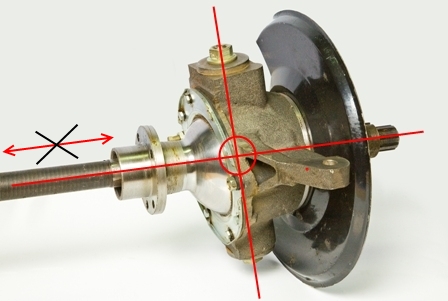
 Very frequent malfunction- departure of the ball bearings that are located in the CV joint. They fly out precisely because of incorrect adjustment of the pins, as a result of which the geometric center of the CV joint and the axle do not coincide. As a result, the axle shaft “walks” in the seat and gradually breaks down. The CV joint itself is also damaged. And when turning, you can hear a crunching sound from the side of the wheel and the wheel may jam. During the repair process, some craftsmen simply throw out all the balls, except for the centering one (additionally welding it) - in order to get rid of the problem of their constant flying out.
 Steering knuckle of the front axle UAZ 469 assembled
 But this does not save for long; there are even cases when the welded ball breaks off while driving, the loads there are so high. It is much more effective to adjust the king pins. It is necessary to achieve a condition in which the line passing through the king pins and the center of the axle shaft intersect at one point. And it is at this point that the center of the CV joint should be located. The displacement of the axle shaft from left to right, as shown in the figure, is unacceptable; it must be rigidly fixed; for this purpose, thrust rings and bushings are provided in the design.
 Space for bushing
 Important! In order for the halves of the CV joint to connect tightly, it is necessary to install a bronze bushing in the ball joint. If you can’t find one in the store, you can install, for example, a connecting rod bushing for a T-40 tractor. Cut it on one side and remove the excess metal a little at a time until it fits snugly into the hole (in the steering knuckle). Then you need to use a 32mm reamer to adjust the bushing to the diameter of the axle shaft. If this is not done, the balls in the CV joint will still fly out.
Removing the Kingpin
Now let’s look at the process of removing the kingpin on a UAZ 469. For this procedure, you can use a special puller, however, it is quite possible to make it yourself. All you need for this is a plate with a hole for a bolt, a washer and 2 nuts. The plate will rest against other bolts around the perimeter, and the center bolt will just pull the king pin out of its seat.
 The process of pressing out the kingpin
 Adjustment
Before you start adjusting, prepare everything you need: bushings for the axle (if there is a groove on the axle), 4 thrust bushings, as well as oil seals. The main condition for adjustment is that the two halves of the CV joint do not dangle, both during straight-line movement and when turning! The procedure is as follows:

During the assembly process after repair, it is necessary to lubricate all the bolts with nigrol so that next time everything can be easily unscrewed. All mating surfaces (the junction of the axle and the steering knuckle housing) must be cleaned of dirt. It is not recommended to lubricate the CV joint with grease, as it is thick. When heated under the influence of centrifugal force, all the grease will be scattered over the walls of the ball joint, and it is necessary that the CV joint balls be generously lubricated. To do this, it is recommended to dilute the solid oil by half with nigrol.
After final assembly and repair, one more important adjustment needs to be made. We are talking about an adjusting rotary bolt. This is the bolt that limits the maximum angle of rotation of the wheel. It is important not to overdo it; do not tighten the bolt all the way - otherwise the wheel will jam. Tighten almost to the end, and then try to turn the wheel (more precisely, the shaft on which it will stand). It is necessary to unscrew the bolt back until the wheel stops wedging. The rotation angle should be no lower than the factory one. Well, now you yourself can repair the front axle on the 469 UAZ!
P.S.: on the rear - there is nothing special to break there, since there are no rotating parts (knuckle, CV joint). Just periodic maintenance, lubricating the parts - and it will last a long time. The most that can break is the gearbox. In general, UAZs, and specifically 469 UAZs, were produced with so-called “military” bridges, which were distinguished by greater reliability and maneuverability. Therefore, many owners of tuned UAZs install them for themselves.
The UAZ-3741 (“Loaf” or “Tablet”) is not demanding on the road surface - it will pass where it is necessary, and not where it can. This is largely due to the front drive axle, which always comes to the rescue - read about this unit, its types, design and operating rules in this article.
The design of the chassis and transmission of the UAZ-3741
Already the first car of the Ulyanovsk Automobile Plant - the famous GAZ-69 - had a 4x4 wheel arrangement, had simply fantastic cross-country ability and was extremely unpretentious. And to this day, the concept of the “people's SUV”, embedded in the legendary “Kozlik”, remains relevant and is implemented in all modern UAZ models. Four-wheel drive also provided in the UAZ-3741 car (until 1985 - UAZ-452), which is better known as “Loaf” (which reflects its characteristic shape) or “Tabletka” (due to frequent use as ambulances and ambulances) cars in the army).
The UAZ-3741 chassis is based on two drive axles with a classic dependent suspension on semi-elliptic springs and hydraulic shock absorbers. Moreover, only in this model the springs have 13 sheets each (in other models there are fewer sheets), both on the front and rear suspension The springs are interchangeable.
The car's transmission has a fairly simple structure; it is also built according to a traditional design without any special features. The transmission contains a 4-speed gearbox with manual control(classic manual transmission), which works in tandem with a two-speed transfer case (has overdrive and downshift gears) - thanks to the presence of a transfer case, the number of possible gears is doubled, which greatly increases the capabilities of the transmission. Torque from transfer case with the help of two cardan shafts transmitted to the front and rear drive axles. In drive axles, the moment is divided into two streams and directed to the wheels, ensuring their rotation.
Separately, let’s talk about the purpose and design of the front drive axle of cars of the UAZ-3741 family.
Front axle of the UAZ-452 car
Device
The front drive axle is designed to transmit traction force to the front steered wheels. The main gear and differential installed in the front axle are the same as those in the rear axle. The axis of the drive gear is shifted to the right from the longitudinal axis of the car by 190 mm.
To transmit force to the wheels, constant velocity joints are installed at the outer ends of the axle shafts, ensuring equal rotation speeds of the driving and driven forks at any angle of rotation of the wheels.
The hinge is located inside the pivot pin, the design of which is shown in Fig. 2.

Rice. 1. Constant velocity joint: 1 - driven fork; 2 - drive fork; 3 - central ball; 4 - driving balls; 5 - hinge assembly
The turning axle assembly, with the help of which the wheel is turned, consists of a ball joint bolted to the flange of the axle housing, a turning axle housing connected to the ball joint using double pins, and a turning axle. A brake shield is installed on the steering axle body.

Rice. 2. Rotary axle: 1- driving fork; 2 - ball joint; 3 and 17 - adjusting shims for kingpins; 4 - kingpin: 5 - steering linkage lever; 6 - steering axle body; 7-1 driven fork; 8 - rotary axle; 9-wheel hub; 10 - hub drive flange; 11 - coupling; 12 - fixing ball; 13 - protective cap; 14 - bolt; 15 - splined end of the driven fork; 16 - king pin cover; 18 - thrust washers of the constant velocity joint: 19 - axle shaft housing; 20 - oil seal
The pivot bearings are assembled with a preload, which is adjusted using shims with a thickness of 0.1; 0.15 and 0.4 mm. The gaskets are installed at the top - between the ends of the steering linkage lever (on the left steering axle) or the lining (on the right) and the steering axle housing and at the bottom - between the ends of the lining and the steering axle housing. The amount of preload in the bearings should be in the range of 0.02-0.10 mm.
During operation, due to wear of the rubbing surfaces of these parts, the preload in the bearings disappears and a gap is formed in them, which adversely affects the durability of the bearings, which is eliminated by adjustment.
To reduce wear on front axle parts and save fuel during long-term vehicle operation on paved roads, it is recommended to disable the front drive wheels.
For this purpose, a movable coupling is installed in the front axle on the splines of the driven fork, the outer splines of which are engaged with the splines of the drive flange of the front hub.

Rice. 3. Clutch position when turning the front wheels on and off
To disable the wheels, you need to disengage the clutch from the drive flange.
To do this, it is necessary to remove the protective cap and, by unscrewing the bolt from the driven fork, install the coupling in a position where the signal ring groove A on its surface is located in the same plane with the end of the flange. The bolt is kept from spontaneous rotation by a locking ball and a spring. Turn on the wheels by screwing the bolt into the fork until it stops.
It must be remembered that engaging the front axle with the wheels off is not allowed.
The front and rear axles have the same final drive and differential, so all instructions for adjusting the pinion bearings, side clearance and mesh contact of the final drive gears and rear axle differential bearings also apply to the front axle.
Maintenance
Maintenance of the front axle consists of performing the same operations as indicated for servicing the rear axle.
In addition, you must do the following:
At TO-1, lubricate the kingpins of the steering axles through the grease nipple of the upper kingpin.
During TO-2, remove the front wheel hubs and, by rocking the axle up and down, determine the presence of play in the pivot pins of the steering axle. If play appears, make adjustments. The adjustment procedure is indicated at the end of the section.
Check the fastening of the steering linkage arms to the steering axles.
Check the maximum steering angles of the front wheels (minimum turning radii).
Through TO-2, perform all the operations indicated for TO-2, but instead of adding lubricant, rinse the hinges and put 300 g of fresh lubricant in them.
To replace the lubricant in the hinges, you need to unscrew the bolts securing the wheel axle to the steering axle body, remove the brake and axle (do not disconnect the flexible hydraulic brake hose), remove the hinge from the ball joint, remove the old grease, wash the joint and the ball joint and add 300 g of fresh lubricant. Install the drive fork of the hinge in place carefully so as not to damage the oil seal in the ball joint.
Malfunctions of the front axle related to the operation of the final drive and differential gears will be the same as those of the rear axle and are listed in the section “Malfunctions of the rear axle.”
Removing and disassembling the front axle
For repairs, it is necessary to remove the front drive axle from the vehicle and disassemble it.
After disassembling and washing the parts, you need to check their condition (wear) and determine their suitability for further work. Worn parts are replaced with new ones.
To remove the front axle from the vehicle:
— disconnect the pipelines of the hydraulic brake drive, shock absorbers, driveshaft, steering bipod, springs;
— roll back the front axle and install it on a stand or stands.
Dismantling the front axle is performed in the following sequence.
Remove wheels and brake drums.
Remove the protective cap from the hub drive flange.
Remove the bolt from the driven fork and remove the sliding sleeve from the hub drive flange.
Unscrew the nuts of the studs securing the drive flange of the front wheel hub. Tighten the two bolts installed on the flange and remove the flange from the splined end of the driven hinge fork.
Remove the front wheel hubs.
Remove the brake support discs and steering axles and remove the constant velocity joints.
Remove the steering linkage lever and the kingpin linings with shim sets.
Unscrew the nuts securing the ball pins and remove the tie rod.
To disassemble the steering axle you must:
— Unscrew the bolts securing the ball joint oil seal;
— press out the kingpins and remove the steering axle housing;
— in case of wear of the oil seal installed in the ball joint, you need to unscrew the bolts, remove the ball joint, press out the oil seal and replace it with a new one.
Disassembly of the front axle housing, final drive shaft and differential, as well as adjustment of the double tapered final drive shaft bearing, differential bearings, adjustment of side clearance and final drive mesh contact must be carried out in accordance with the instructions made for these components in section "Rear Axle".
Constant velocity joints are disassembled in the following order.
Mark with paint the relative positions of the driven and driven forks.
Clamp the drive fork in a vice in a horizontal position.
Having turned the central ball with the flat towards one of the leading balls, move the driven fork to the side and remove the ball (passing past the flat).
Remove the remaining three balls in the same way.
The hinges are assembled in the following order.
Clamp the drive fork in a vice in a vertical position.
Install the central ball into the spherical recess of the drive fork with the flat to the side.
Place the driven fork on the central ball.
Turning the driven fork to the side, install three driving balls into the grooves.
Move the forks to the maximum angle and, turning the central ball with its flat side towards the fourth groove, insert the last (fourth) ball that will pass by the flat of the central ball.
The preload in the hinge between the balls should be such that the moment required to rotate one fork from 10-15° in all directions from the axis when the other fork is clamped in a vice is equal to 300-500 kgcm.
To ensure correct assembly and the required preload, the balls are sorted into 9 groups. Each hinge is assembled with balls of one group or with balls of two adjacent groups, for example, two balls measuring 25.41 mm and two 25.44 mm.
When installing, balls of the same size must be placed diametrically opposite to one another.
The difference in diameters of two pairs of balls of one joint is allowed no more than 0.04 mm.
If you have a stand, roll the joint on it at a varying angle from 0 to 30° for 2 minutes at a rotation speed of 300 rpm.
When running in, lubricate the joint with stub axle lubricant.
Front axle assembly
The front axle must be assembled in the reverse order of disassembly. All instructions for assembling the rear axle also apply to assembling the front axle. In addition to these guidelines, the following must be taken into account.
Press the bushing into the pivot pin flush with the end of the socket under the thrust washer.
The oil grooves of the thrust washer installed on the trunnion journal should face outward (towards the driven fork flange).
The seating surface of the pivot pin must be lubricated with a thin layer of red lead, shellac or UN-25 sealing paste.
Before assembling, lubricate the pins with liquid lubricant.
When installing the joint, apply the lubricant specified in the lubrication chart to the ball joint and joint.
When installing on the driven fork, lubricate the sliding coupling of the hub drive flange with a thin layer of lubricant 1-13 to protect it from corrosion.
Lubricate the pin bearings through grease nipples with press grease “C” or grease oil “C”.
The oil-removing ring of the oil seal of the drive gear of the front axle, installed between the flange and the inner ring of the bearing, has grooves at the end with the right direction of the turn and is marked with the letter “P”.
Oil removal ring installed in rear axle, has left-hand grooves and is not marked. Oil removal rings must not be mixed up, otherwise oil may leak from the oil seal.
After completing the assembly of the front axle, it is necessary to check the angles of rotation of the axles in each direction and the alignment of the wheels.
After assembly, the front axle is checked on a stand under load and without it.
A properly assembled front axle should not have increased noise, heating or oil leakage through the oil seal, covers and bolted joints during operation.
The procedure for adjusting the bearings of the pivot pins is as follows.
Jack up the front axle.
Unscrew the wheel nuts and remove it.
Unscrew the bolts securing the ball joint oil seal and move the oil seal away.
Check for axial play at the pins by moving the steering pin body up and down with your hands. If there is play, make an adjustment, for which:
Unscrew the fastening nuts and remove the lever to the bipod rod on the left pivot pin, and the kingpin plate (on top) on the right pivot pin, remove the thin (0.1 mm) adjusting shim and install the removed parts in place.
Unscrew the fastening bolts and remove the king pin trim (bottom), remove the thin (0.1 mm) adjusting shim and install the king pin trim in place.
To maintain alignment of the cardan, shims of the same thickness should be removed from the top and bottom.
Check the build results. If the play is not eliminated, re-adjust by removing the thicker gasket (0.15 mm) and installing the thin one (0.1 mm) in place.

