20.10.2023
We connect the car radio at home, with our own hands. DIY music center from a car radio Make a speaker with a car radio and speakers
Development digital electronics noticeable not only in the rapid obsolescence of computer technology, but also in the rapid obsolescence of automotive electronics.
Using car radios as an example, almost all available advances are built into this equipment; along with the improvement in consumer properties, their price is significantly reduced. The once unaffordable MP3 car radio, a car audiophile's dream, now costs just over 1,000 rubles. This situation leads to the fact that completely functional unnecessary devices appear in the household. Somehow, by the will of fate, I was for a long time 150 km from a big city. In inclement weather, I had to while away the time watching the TV, which in our age of progress shows only two terrestrial channels, or rather two zombie channels. FM cell phone received only one radio station with a wide repertoire heavily mixed with gopstop songs. It was here that I remembered the old car radio I had taken out of the car. Due to the availability of free time, I decided to make a stationary homemade radio receiver with the ability to receive the Mayak radio station in the mid-wave range. Moreover, all the additional parts in the form of a loudspeaker and power supply were present, and the loop antenna remained after the manufacture of the detector receiver.
How to make a radio receiver body with your own hands
I decided to make the body from pieces - scraps of OSB boards. The blanks were cut out with a jigsaw.
1. The receiver will require six blanks:
— front panel frame for mounting a car radio measuring 260mm×95mm;
— front panel for speaker 260mm×240mm;
- side wall, height 330mm, base 240mm, top 260mm, two pieces required;
— top cover 262mm×260mm;
— bottom cover 230mm×260mm.
The external dimensions of the radio receiver box are as follows: width 275mm, height 330mm, depth 260mm. Blanks from the front side polished emery cloth.
2. The issue of final finishing of the receiver has not yet been resolved, so for freedom of thought I decided to assemble the case using PVA glue. We begin the assembly from the base of the receiver; to do this, in the place where the side walls are attached, we use self-tapping screws and glue to attach two slats with a cross-section of 25mm×25mm.
3. I glued the same bars in the places where the side walls of the top cover were attached; here I did not use self-tapping screws; I applied clamping force for gluing using clamps. Drying time for each glue is 24 hours.
4. I glued the side walls to the bottom and lid. We press the walls against the slats with clamps. Be sure to check the diagonals of the box, the measurements should be the same. If something is crooked, it’s better to fix everything at this stage.
5. After the gluing of the box had dried, I glued the slats along the contour of the fastening of the future back cover, and also glued the slats in the places where the front panels were installed. I used clamps for fixation.
6. Carefully marked and cut out a cutout on the radio mounting panel in the center of the upper part, 178mm wide and 50mm deep.
7. In the center of the speaker panel, I drilled a hole with a diameter of 113 mm for the speaker. You can use old working ones or other loudspeakers as a speaker. You can immediately drill the mounting holes. An unpaired speaker, left over from the published design, is installed in this design.
8. Before installing the panels, be sure to sand their front part with sandpaper, then it will be more difficult to do this.
9. Glue the panels into the box. Finally dry all connections.
10. Sanded the box from the ends and from the adhesive joints.
11. The box must be thoroughly cleaned of dust.
12. I cut the back wall with dimensions 320mm×270mm from a piece of treated fiberboard. I drilled holes with a diameter of 10mm in the wall according to the markings. The wall is attached to the body with four self-tapping screws.
13. The receiver body can be covered with parquet varnish, puttied and painted or covered with veneer.
Radio assembly
1. I used a small-sized Chinese one as a power supply pulse block power supply, but any power supply with a 12 volt output and a load of 1.5-2 Amperes will do. The power supply was placed on a plastic panel attached to the wall of the box. The power wires of the car radio are stripped and connected to the terminals of the power supply.
2. Installed the speaker and the panel for the protective mesh.
2. I decided to make the antenna built-in. For the experiments, a frame was assembled from scrap materials. The diagonal size of the frame is 200mm; 16 turns of enamel-insulated wire are wound around the frame. I connected the frame to the receiver and received the Mayak radio station on medium waves at a frequency of 549 kHz. Subsequently, the frame was modified and made from a CD with the mirror layer removed. I would like to note that several old car radios were tested, the Pioneer DEH-3700MP device completely refused to work on the CB with a frame and asked for a piece of wire 1-1.5 meters long.
3. I attached the frame to the side wall of the radio box.
4. I secured the car radio in the box using a bracket made from four pieces of mounting tape. At one end the bracket is attached with a nut to the radio, and at the other end the bracket is secured with a screw to the bottom cover of the box.
car radio at home, DIY speakers
The idea of creating a monoblock from a car radio and car acoustics arose because listening to music in a car is noisy, and you can only enjoy the sound quality when the engine is off. I decided to remove these musical devices from the car, and when, on occasion, shelves from a chipboard wardrobe came to hand, I decided to make a candy bar for the house, because the music in the car sounded very good and these components should not be idle in vain.
After reading articles about creating speakers (acoustic systems), and first of all finding out the possibility of powering the radio from a PC power supply, I found out that it would be possible to power it and carried out a test connection of the PC power supply, a radio with one speaker. Everything works.
After reading about the design of speakers (speakers), I took the easy route - without calculations, but made from what was available.
Type of speakers - design in place in the car (speakers on the rear shelf) - called a screen or shield - open design. The sound of this performance is of the highest quality. I chose the ZY type (closed box) for execution - it’s easier to make.
Wall material: chipboard, MDF. plywood is not allowed, because they are flexible and will resonate. I used some chipboard I found for free. When designing speakers, consider that the larger the volume of air in the box, the better (softer bass) (but it is better to calculate).
I laid out the shelf in such a way that there was maximum volume left for the columns. I made the markings, used a jigsaw for sawing, then you can level the edge either with sandpaper by hand or with a grinder with a flap wheel. To connect the walls, it is better to use a furniture euroscrew.
Be sure to make the fastening of the walls thorough, do not spare screws, so that the rigidity of the structure is at the proper level, so that with large sound load They did not add their own overtones to the walls.
After marking for the screws and drilling holes for them, assemble the entire monoblock structure with all the screws in order to ensure the correct location of the fasteners before the main assembly. If everything is assembled well, we proceed to the main assembly of the monoblock. To tighten the screws, I used a screwdriver with a 4 mm hexagon, which I sawed off with a grinder from a furniture key (straight section of the key). You need to understand how the load is distributed inside the column from maximum to minimum: front walls - rear walls - side walls - top - bottom. When assembling, we coat all joints with silicone sealant (+ a gun for a tube with sealant). According to the closed box theory, sound waves should remain inside the box and not leak out through cracks. This is how I assembled the monoblock except for the bottom wall; through these holes I will insert the remaining parts.
Screwed the speakers into place. At first I used the screws that came with the speakers, but then I started using wood screws - they are better in this case.
My arrangement of parts is as follows: speakers on the sides, each in a separate column, radio in the middle at the bottom, power supply at the top at the back. I sawed with a jigsaw the first time, so it didn’t work out well.
The next step is to strengthen the corners. We glue it with square or triangular glazing beads using PVA glue (I used something like Yaroslavl PVA_M - it worked well). It is clear that the wood must be dry, smooth and sanded.
We install the power supply before installing the radio (it is more convenient to screw the mount). Then the radio.
In order for the power supply from the PC to work in our case, we need to start it. Place a jumper on the large connector (green with any black wire), a paperclip will do.
Let's take 12 V from any yellow wire. earth - any black. It is advisable to check with a multimeter. If you will no longer use this power supply for a PC, then it is better to choose 3 yellow wires and 3 black ones. checking if they are all the same. connect, increasing the cross-section of the wire for power supply. It is better to cut the remaining wires so that they do not interfere. I didn't cut it because... Perhaps the block will still be used in a PC. It is better to solder all wire connections.
Next, it is recommended to fill the volume of the speaker with sound-permeable material without touching the diaphragm in order to reduce the sound speed. waves, reduce the load on the walls. I filled it with padding polyester, but when I checked the sound, I removed it because... the speaker became bright (a lot of highs and mids, low frequencies became very small). Before laying the padding polyester, I checked it without the bottom wall. The sound is garbage! the entire candy bar was on the floor (1 photo).
Next, I assembled the bottom wall with sealant and listened - again there is little low frequency, better than with padding polyester, but not like the first listening on the floor without a bottom. I will assume that the floor or table serves as a lower wall with a large area + the slots at the bottom play the role of a bass reflex (random). But the sound was definitely the best without the bottom wall on the floor. Those. After building the monoblock, you need to adjust the sound of the speakers to suit your desires (with a bottom wall or not).
Bottom line. When I finished assembling, I realized how it really should have been done.
- There is no need for large holes in the back wall. The fan of the unit blows from the inside to the outside, so heat will be removed from the radio. Enough at the bottom under the radio 1 and in the middle 2-4 holes of 30mm (they were there).
- Attach the power supply slightly inward so that its rearmost point (the button) does not protrude beyond the plane of the panel so that you can turn the box.
- Install the radio only after securing the power supply.
- Use wood screws when attaching speakers.
Costs: PVA glue 2*23, spent 11 rubles, universal sealant 112 + device for it 85, rulers 150, euroscrew 50 pcs-50 rubles, moving costs. the rest is yours or free.
Conclusions. The unit is fully functional and the sound is decent for these components. The box turned out to be heavy (about 30 kg), so it’s easier to carry it with two people. It is better to make calculated speakers with normal speakers, but this is more expensive and more complicated. On the electrical side, everything is simple in this version.
For my speakers, a larger volume speaker is better. you can make not a monoblock, but 2 large speakers and 1 source with power and appropriate connections for switching.
After listening, I will share my impressions. Best regards, EA.
Hello to all DIYers! A friend recently gave away a burnt car radio, purchased in a hypermarket with working USB and FM. Connected to power - it worked. I disassembled it further, a piece of plastic was knocked out on the output microcircuit - everything is clear, the outputs are short-circuited. I decided to restore it, fortunately I got a three free days, and I recently collected it.
I bit out the output microcircuit, soldered the power supply, inserted the flash drive and started checking the signal with a probe. I found the left and right sound channels. I connected it to the TA8205 and almost went deaf from the distortion and 50 Hz background. 3 hours of tambourines and dancing and a solution was found. There is a 30 kilo-ohm resistor at the input. But I still couldn’t figure out the power supply; I had to install a small 12-volt transformer and a stabilizer on the Krenka for the radio.

The sound turned out to be more or less decent and powerful, perfect for a garage. I decided to tinker with the case, then in the garage I found a plastic speaker that matched the size of the front panel of the radio, and sawed more than half of the case with a grinder. I cut out a window for the panel, a radiator, a switch, terminals for the speakers, and cleaned it with a file. The transformer for the amplifier was installed from the center and is switched on via a relay from the signal from the radio itself. I fastened everything together with bolts and with hot glue.

Well, in addition, I decided to adapt output power indicators on LM3915 into the case, fortunately I had 2 pieces in my stash and recently bought 500 pieces of 3 mm from the Chinese. LEDs for 250 rubles. I drew 2 scarves for microcircuits and LEDs with a marker, the printer ran out of toner. I soldered the whole thing, connected it - it works. It turned out to be quite good, a la music center. The photographs show the entire assembly process.
Photo of the music center assembly process


LED sound indication


Music is something that many people cannot give up, either at home, on vacation, or even while driving a car. And everyone knows what is needed for music! No, we are not talking about instruments, orchestras and performers, we are primarily about devices that are able to reproduce it. In our house it’s a stereo system, in nature it’s a portable radio tape recorder, and in the car there’s a radio tape recorder. What to do if you have a car radio and need to listen to music at home? In fact, a car radio is quite capable of replacing a music center; here you just need to supply power to it, connect the acoustics, and also think about the case. It is this option for upgrading a car radio, when you can turn it into a music center, that we will talk about in our article.
What to take as a basis for a music center from a car radio

So, we roughly know what we need:
Power unit;
- acoustics;
- frame.
...so how can we try to implement all this with minimal costs? If you look around and take a closer look, you can find things that meet our requirements in almost all respects, while the investment in them is minimal. For example, an old system unit, if you remove all the already “used internals” from it and provided that it has a working power supply, then this is simply an ideal option for our case. We will continue our story about how to make a music center from an old computer system unit and car radio.
The process of making a music center from a car radio and a system unit with your own hands
First of all, we need to find our donor. In our case, this is an old system unit, but with a working power supply. To install the radio in the case, you will need to work on it. The first step is to remove the partition for installing the motherboard.

Next, you will need to cut a window on the front side for installing the radio. It is best to place this window a little lower, for stability, and in a place where there is a solid tin plate, for better rigidity during installation.

In any case, after installing the radio, it will have to be additionally attached to the body using improvised corners and ribbons, which can be cut from the removed partition.

You will also need fasteners, of course.

Now, after the mechanical installation of the radio is completed, we proceed to installing the acoustics. Of course, this cannot be called real acoustics, there are only 4 speakers, and thin tin walls from the sides of the system unit, in which mounting holes for the speakers are cut.

You can cut holes using a jigsaw.

In order for the walls to be a little stiffer and the sound to be correspondingly better, you can glue additional soundproofing material to the walls, like the one used for soundproofing cars.
Now after mechanical part The installation of the car radio is completed, and the music center has almost acquired its final external features, you can begin to electrically connect the radio.
Electrical connections of the music center from the radio to the power supply of the computer system unit
Initially, it is necessary to provide power to our radio - 12 volts. This voltage can be produced by our power supply, it’s not in vain that we took it... But it won’t just turn on, you need to short-circuit the green and black wires on it, only after that it will start working.

It is best to turn on the power supply, and therefore turn on the radio, through a switch that can be mounted in a place convenient for you. In our case, at the top of the system unit.

Now we connect the radio. Radio tape recorders usually have standard wires with color coded to connect it (ISO connector).

The pinout and designations of wires for connecting the radio are shown in the figure below. Now there will be another problem. Since the memory of the car radio is volatile, you will also have to provide additional power to the yellow wire, or re-tune the radio each time you turn it on. In our case alternative source power supply is provided by the battery, it is not necessary to buy some kind of new battery, because the radio's power consumption in standby mode is minimal, which means that even an old and weak battery will last for a long time.
That's it, now all we have to do is assemble the system unit back, installing the battery in it and closing the side walls with the speakers installed in them, connecting the antenna to the radio socket.

Based on the results of the work, we got a music center assembled with our own hands. It may be somewhat inferior in performance characteristics to the music centers that we are used to seeing every day, but it was assembled from improvised devices and materials, which for some will be of decisive importance.


It may be somewhat inferior in performance characteristics to the music centers that we are used to seeing every day, but it was assembled from improvised devices and materials, which for some will be of decisive importance.
Today, several ideas are being discussed online on how to make a music center with your own hands. On our portal we decided to keep up with life, put our ideas together, and present the result to the attention of our readers. It’s exciting to think that it’s possible to assemble a functional music system from a single purchased and inexpensive part using old junk. The craft is interfaced with an amplifier, for example, for an electric guitar. As often happens in life, the main task is to assemble disparate parts, as well as protect the equipment from improper use. Let's see how to make a music center with your own hands.
What to assemble a music center from
Invention is the ability to use someone else's parts to create new things. For example, microcontrollers have long been part of complex hardware, but their use has never looked as simple as at the beginning of the 21st century. Embedded microsystems allow you to play a lot of formats, including flash memory cards. This allows the use of chips to decode the signal. Most cost 1000-2000 rubles and are complemented by a control panel.
The supply voltage of the devices is +5 or +12 V, which makes it easy to pair digital equipment with a standard computer power supply. Amplifier chips are available on the shelves of online stores and capital markets; it is possible to separately dial equalizers and other elements of the music system along with adjustment knobs. This allows you to design acoustic conglomerates according to your own needs.
The video on YouTube discusses the possibility of creating your own music center from the MP2896 embedded microsystem. There are many others on sale. The advantage is the possibility of choice. Make good use of your old music system. It is known that contemporaries no longer needed cassette recorders; the two lower decks were removed along with the preamplifier heads and other unnecessary things. Inside there is a radio with a disc player. By the way, replace the latter with a DVD drive, the only problem is recognizing the format.
Instead of decks, all that remains is to install a couple of modern ones full-range speakers to get some kind of boombox. Plus in beautiful appearance, convenient adjustment elements, no external speakers. There is already a power supply inside, which is an additional big plus. Old technology did not know USB standards, therefore, embedding a card reader or an integrated microsystem like the one mentioned above will be an integral part of the procedure. Our readers will look at some new equipment on the website electronshik.ru, where prices are also displayed. Here are the characteristics of the MP2896:

- Supply voltage +5 V.
- Permissible supply voltage variation ±0.25 V.
- Current consumption 100 mA.
- Connector type MU 2F, MU 3F.
- PCB connector type MW 2M.
- Input interfaces SD, FM, USB, AUX.
- Digital clock.
- Four equalizer settings.
- Input and output voltages through information channels are 0.25 - 0.5 mV.
There are restrictions on the media file system and control panel. As a result, we see a device with a supply voltage of 5 V, which reads flash drives, receives radio broadcasts, and passes the generated external sound through an equalizer. All that remains is to add a low-frequency amplifier and speakers to get a workable system.
Homemade music center power supply
The supply voltage of the computer power supply is ideal for the projected modern devices, +5 and +12 V. The microsystem is powered from the first line, and the battery is charged from the second (you will need to purchase additionally). In the absence of a network, the music center operates autonomously. To provide the required 5 V and not overheat the microcircuit, a ready-made converter circuit is presented on the website sinava.ru DC voltage 12-5 V.
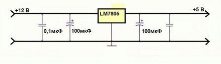
The figure shows that the LM7805 chip converts the voltage to the desired format. Capacitors are soldered in to filter harmonics. Electrolytic ones have a breakdown voltage of 25 V, others (with straight plates in the diagram) - 50 V. Do not forget to place the elements with the correct polarity. For convenience, the diagram shows the positive electrodes electrolytic capacitors are indicated by pluses. And it is better not to turn on the microcircuit at high voltage so as not to overheat.
Other interesting things: on YouTube they suggest making separate power switches in the music center for the low-frequency amplifier and the built-in microsystem, and connecting the jack connector to the amplifying stage. As a result, it becomes possible to use the box as an amplifier for an electric guitar. Think for yourself which chips to add for effects inside. It is not prohibited to use the aux input at the same time. This gives you a chance to play along with your favorite artists or sing karaoke. The accompaniment, of course, should already be present on the flash drive.
Please note that the low-frequency amplifier gets very hot during operation. The host chip must be located on a large heatsink made of aluminum or another metal that conducts heat well (copper). Using a similar feature, it is possible to isolate the required element from the design of an old factory music center: if you are looking for the heaviest loaded key (with a massive radiator), it is most likely the most necessary one.
This is where the wires go to the speakers. Paths along printed circuit board trace with the armed or naked eye.
It remains to understand what supply voltage was used in the old equipment in order to connect everything together. It is necessary to calculate the input and output voltages:
- We believe that professionals designed devices based on generally accepted standards in order to assemble complex systems piece by piece.
- In the case of over-amplification, this can be heard in the sound distortions generated by the meander. Any music performed in this manner is reminiscent of thrash metal; the cut off tops when the transistors exit linear mode are hard to miss by ear.
- The elemental base of modern times supports wide ranges signals.
By the way, take a power supply from a Soviet portable tape recorder (if the computer one doesn’t suit you). It is not a fact that the indicated voltages will be found there, but we have already provided a 12-5 V conversion circuit (you will find others by analogy). We believe that it is possible to get something similar for every occasion. Do it computer unit the food is not light in weight, therefore, carrying iron is not much fun. The PC unit is designed for power consumption above 350 W, which simply by definition is not useful in a homemade music center.

FM modulator
Music center on FM modulator
Today, motorists are offered an interesting feature: listening to flash media through the car’s receiver. A key fob is used where the memory device is connected. Then the FM modulator works like a walkie-talkie. Emits radio waves that the car's receiver can pick up. Both devices are tuned to an arbitrary FM frequency, and nearby listeners (receiver owners) enjoy the content from the flash drive.
The invention is based on the fact that the transmission power is low. However, it is sufficient for the components of the music center to work in harmony. An FM modulator is used to create autonomous systems. If you assemble a music center and include a receiver (any old Soviet one), you will be able to listen to flash drives on decent speakers, even in a car. The gadget is powered by a cigarette lighter; the battery is suitable as a source, just like a computer power supply.
It is possible to make a music center yourself, as indicated, if you have already purchased an FM modulator. There is no need to add an amplifier; the receiver has a built-in one. But for working with large speakers, an extra cascade will not hurt.
Don’t forget that speakers are packed with electronics for good reason: radio equipment doesn’t like vibrations, especially powerful ones low frequencies. For this reason, it is not possible to collect electronic components in one box. best idea. It’s ideal to plug a couple of speakers from an old tape recorder into the box. We believe that loudspeakers are designed to coexist with electronics without causing mutual harm.
Note! For smart people who underestimate the role of vibrations, we recommend reading about the reasons for the crash of the space shuttle Columbia in 2003.
An FM modulator can be purchased for about 300 rubles. If you have an old receiver and can assemble a low-frequency amplifier, be sure to try it. Any Tourist will do. If a station appears on the working channel of the FM modulator, you just need to rebuild it and the receiver. This is not very convenient when constantly changing broadcast zones.

