30.10.2023
New hybrid amplifier circuits. Magnat hybrid amplifiers: how a tube and a transistor became friends. Now let's look at the lamps
The Magnat company can hardly be called a newcomer to the audio market, but from time to time it surprises with its courage - it takes on directions completely unknown to it. And he succeeds.
The Bulldog is a good-natured but unyielding dog. It was the bulldog's muzzle that graced the Magnat logo from the very beginning of its existence (although ten years ago the bulldog left the logo). The company was founded in 1973 in Cologne by engineer-enthusiast Rainer Haas and the number of his employees at that time did not exceed 60 people. During the 70s Magnat became one of the leading manufacturers acoustic systems, and in 1983 entered the Car Audio market. Automotive electronics are something the brand has long been associated with, but in 2007 the peace of hi-fi players was disturbed by an unexpected debut.
Tube debut
The Magnat RV 1 push-pull amplifier inherited all the best from the tube classics of the 60-70s. The topology was based on low noise 12AX7EH dual triodes and 12AU7 tubes in the pre-section, as well as EL34 pentodes in the output stage. There was even a MM/MC corrector for 4 12AX7EHs. The idea of developing a full-fledged tube amplifier Audiovox export manager Mario Lode, who was in love with the group AC/DC, suggested to the designers. The RV 1 was followed by the successful 50-watt amplifier RV 2 with carefully selected pairs of dual driver triodes 12AX7 (ECC82), 12AU7 (ECC82) and 6550 output tetrodes. It is noteworthy that all amplifier tubes were manufactured in Saratov.
 The first hybrid tube-transistor amplifier from Magnat - RV 1, was produced from 2007 to 2012
 Another bold decision by the Magnatists was the idea of introducing a pre-circuit with dual triodes ECC88 (6922) into the output circuits of the SACD player, which led to the creation of the MCD 850 model with a Burr-Brown PCM1796 DAC and an R-core transformer in the power supply . The 6922 dual triodes do not act as amplifiers here, but are responsible for impedance conversion, allowing for a low output impedance. The same applies to the MCD 1050 CD player, which uses similar tubes. The model is equipped with an upsampler, a Burr-Brown DAC and can work as an external DAC with S/PDIF and USB inputs (24 bit/192 kHz).
Magnat RV 3: listen for hours
For the 40th anniversary of Magnat in 2013, the flagship RV 3 appeared (its review is on the website -). Sandro Fischer, R&D Director, comments: “We actually discussed all possible options, including pulse amplification. At some point, a decision had to be made, and here the personal love for lamp technology of one of our managers played a role. But we had no illusions about tubes: they, just like transistors, can make both good and bad sound. We like the hybrid design where the tube is used in the preamp. Perhaps it determines only 20% of the sound character, but the equipment with small-signal vacuum devices turns out to be simple and reliable, and if everything is done correctly, it is pleasant to listen to music for hours. And for us this is one of the most important criteria.”
 Hybrid tube-transistor amplifier Magnat RV 3
 The RV 3 model has become the absolute embodiment of the “hybrid” concept in the company’s lineup. The amplification at its input is carried out by the SRPP section (cascade with dynamic anode load), which has negligible distortion and high linearity. It uses a carefully selected pair of dual ECC82 triodes Russian production, which ensures perfect channel identity with minimal variation in characteristics. The discrete output of RV 3 is assembled using high-current Toshiba transistors. The open design of the model is made in an industrial style and looks similar to the engine of American muscle cars, which the company’s chief Shandro Fisher likes so much. The fan-shaped fins of two cooling radiators symmetrically located on the top panel resemble the needles of a bristling hedgehog. ECC82 are also installed there, surrounded by protective ring turrets, a casing with a 650 W toroidal power transformer and a cylinder hiding a set of power supply capacitors.
 Hybrid tube-transistor amplifier Magnat RV 3 (rear view)
 The RV3's 8mm milled aluminum panel is bisected by a highly polished ALPS motorized volume attenuator knob, also made of aluminum. On the left side of the facade there is a power button and a balance control, on the right there is an input selector for reed relays, a round OLED display showing the input, and a headphone jack. The amplifier produces 150 W per channel (8 ohms), and the high damping factor allows it to work with virtually any speaker. You can control the RV 3 using a metal remote control.
 Magnat RV 3 hybrid tube-transistor amplifier, ECC82 tube (left) and aluminum remote control (right)
 The advantages of the hybrid design are that the tube pre-stage helps achieve natural analog sound, and the transistor output provides stability, accuracy, dynamics and allows you to be more loyal to the choice of speakers. RV 3 vacuum triodes have a linear transfer characteristic, short harmonic spectrum and high input impedance, which helps optimize the amplifier's input impedance. As a result, it is possible to obtain a natural tone of sound, woven into a pattern of characteristic sound delivery. modern amplifiers with a powerful transistor exhaust that guarantees precise and dynamic sound. By the way, Sandro Fischer is convinced that it is tube technology that will become a “bait” for young people, since even compressed files passed through a triode acquire charm and nobility.
Hybrid democracy
German engineers also succeeded in implementing the idea of hybrid designs in the classic Hi-Fi line of amplifiers (MA400, MA600, MA800, MA1000) and even in more “democratic” models - the MC 2 audio system, the MC 20 CD receiver and the MC 1 SACD receiver.
The tube-transistor MA 1000 with a power of 80 W per channel has a more traditional design, unlike the RV 3. Its pre-stage is built on two dual ECC82 triodes that have undergone a 60-hour factory warm-up. The output contains Toshiba transistors. The power supply unit has 4 electrolytes of 10,000 μF each and a toroid. In combination with the MA 1000, we recommend the MCD 1050 CD player that matches its parameters.
 Hybrid tube-transistor amplifier Magnat MA 1000 (with cover removed)
 The MA 800, MA 600 and MA 400 amplifiers use a similar tube-transistor base. The MA 800 integrated circuit differs from the MA 1000 in power (2 x 75 W at 8 Ohms), has a topology of circuits such as “dual mono”, “pre” on ECC82 lamps and an output on high-current Sanken transistors. Each channel is powered by a separate winding of a toroidal transformer. The aluminum panel features tube windows and the same controls as the MA 1000. The circular OLED display features a pair of indicators to indicate the use of one of the MM/MC phono inputs. The MA 800 model has similar switching, but does not have a preamplifier output.
 Two ECC82 tubes on the input stage of the Magnat MA line of Hi-Fi amplifiers
 The younger “hybrids” MA 600 (2 x 55 W, 8 Ohm) and MA 400 (2 x 32 W, 8 Ohm) have a different design, use only one ECC82 lamp in the pre-stage and also have a semiconductor output. The MA 600 has a built-in Burr-Brown DAC and a Bluetooth module with aptX support for lossless formats. There is a full range of analog and digital inputs, including MM phono jacks and an asynchronous USB port (24-bit/192 kHz). The closing MA 400 series received an MM phono preamplifier with low-noise op-amps and an infrasound filter. The power supply has two 10,000 µF capacitors.
 CD player Magnat MCD 1050 with tube preamplifier
 The Magnat line includes the MC 20 hybrid CD receiver with one ECC88 tube in the input stage and Thomson Audio chips in the output stage. The model is assembled in an aluminum case with wooden sides, has a CD drive, an AM/FM tuner with RDS and advanced switching, including a USB port, mini-input jack, subwoofer output, etc. The built-in amplifier develops 30 watts per channel. The MC 2 kit is available, including the MC 20 and two bookshelf speakers. Hybrid SACD receiver MC 1 with a power of 2 x 60 W, is equipped with a similar lamp at the input, and has Sanken transistors at the output.
 Hybrid CD receiver Magnat MC 20
 Magnat's focus on hybrid amplifiers has brought it well-deserved success. Currently, Magnat produces components for Car Audio, DC, Hi-Fi and is even setting up the production of headphones - judging by the latest data from a test laboratory in Pulheim-Brauweiler near Cologne. This bulldog will teach the young people new tricks.
So. As I wrote earlier, I have a desire to make an amplifier for a bass guitar. I went through several options and made a decision. I refused the option of a purely tube amplifier due to the large size and high cost of the output transformer. It was decided to collect hybrid amplifier.
Here is an example block diagram. Everything will be collected in one small building.

" " on Yandex.Photos
It's a mixture tube stage pre-amplifier (in my case) and transistor or microcircuit final amplifier
The tube pre-amp is made according to the classical design, one tube (double triode) for 2 stages. 2 volume knobs (gain and master) with a tone block between them.
To be continued.

" " on Yandex.Photos 
" " on Yandex.Photos 

Having reviewed the principles a little, let's try to make a pre-amplifier using this circuit as a basis.

Tube pre amplifier
We are developing a board, since it is really easier to etch it than to invent something with a canopy.
Here is a visual diagram of the pre-amplifier; we deviated a little from the original plan. So I decided to try this scheme preamplifiers. Actually, the pre-amplifier ends (if you look at the diagram) where from pin 8 there is a contact for 2 capacitors of 6.8 mKF each. In this article we will only consider the property itself tube pre amplifier.
The board was developed in the layout 5 program, so you can download the file for it.
The file contains a circuit template and the program itself, in the layout 5 program in macros in the user folder there are 2 templates for lamps, the macros were made by my friend but they are suitable for ordinary finger lamps and the second for an octal socket.
Let's go back to our pre-amp. I suggest using 6n2p (6n2p-ev) lamps, with a dividing grid installed on the 9th leg. Which, logically, can hit the ground and probably! I emphasize that there will probably be fewer interferences. But in reality I haven’t checked it yet.

Hybrid amplifiers are different high quality sound and ease of execution. We offer you enough simple diagram manufacturing that uses simple components. Using such a hybrid amplifier will allow you to get enhanced, clear and detailed sound at the output.
Zarathustra amplifier circuit
More detailed and well-presented information can be found from the author of this amplifier on the forum:
Hybrid amplifier Zarathustra
One of the features of hybrid amplifiers is output current limitations. At the same time, the amplifiers are characterized by stable operation and minimal heating. No need to perform additional systems cooling. The output current is equal to the output current of the cascade, and can reach 15A.
It is possible to operate in supply voltage mode. Improved cascade symmetry at high frequencies allows you to significantly improve sound quality when operating at maximum volume and when playing high frequencies. Minimal distortion has a positive effect on sound quality.
To manufacture a hybrid amplifier, an SRPP output stage was used on bipolar transistors, two 6E5P lamps are installed at the input. The use of a tetrode cascade ensures voltage stability and excellent output voltage performance. The output stage uses a virtual average using capacitors instead of bipolar power supply.
This allows you to eliminate the appearance of a load in the circuit DC and avoids overcharging the power supply. This eliminates impulse distortion that can occur at peak power levels. The output signal is connected to the midpoint, and the capacitors used are eliminated from the audio circuit. This eliminates the influence of capacitors on sound quality.
Capacitors are connected to the windings, which makes it possible to suppress the electrical background in the incandescent circuits. This improves the sound quality. The use of capacitors makes it possible to make the filament voltage on the output filaments completely symmetrical. At the same time, the implemented amplifier is simple and can be easily implemented by every radio amateur.
We also note the affordable cost of the components used. If in the manufacture of other amplifier circuits it is necessary to use high-quality foreign capacitors, then in this case it is possible to use inexpensive domestically produced capacitors. The influence of their quality on the generated sound is minimal, which allows us to slightly reduce the cost of manufacturing the amplifier without losing sound quality.
At numerous requests from radio amateurs, I present an improved and more complete circuit of a hybrid ULF with detailed description, parts list and power supply diagram. The lamp at the input of the 6N6P hybrid ULF circuit was replaced with a 6N2P. You can also install the 6N23P, which is more common in old lamps, in this unit. Field-effect transistors are replaceable with other similar ones - with an insulated gate and a drain current of 5A and higher. Variable R1 - 50 kOhm is a high-quality variable resistor for the volume control. You can set it up to 300 kOhm, nothing will worsen. Be sure to check the regulator for the absence of rustles and unpleasant friction during rotation. Ideally, you should use ALPS RG - this is a Japanese company producing high-quality regulators. Don't forget about the balance regulator.Trimmer resistor R5 - 33 kOhm inserts voltage zero on the speaker in ULF silent mode. In other words, by applying power to the transistors and instead of a speaker (!), connecting a powerful 4-8 Ohm 15 watt resistor, we achieve zero voltage on it. We measure with a sensitive voltmeter, since it should be absolute zero. The diagram of one hybrid ULF channel is shown below.

The remaining resistors are 0.125 or 0.25 watts. In short, any small ones. A 10,000 µF capacitor can be safely reduced to 100 µF, but it is drawn according to the old designation. We set all capacitors for anad supply to 350V. If it’s difficult to get 6.8 μF, set it to at least 1 μF (that’s what I did). The quiescent current control transistor will be replaced with KT815 or KT817. This will not affect the sound, it simply corrects the current there. Naturally, we need another copy of the hybrid ULF for the second channel.
To power the transistors, you need a bipolar source of +-20 (35) V with a current of 4A. You can use a regular transformer. Since more power was not required, I installed a 60-watt trans from a VCR with a corresponding reduction in output power. Filtration is simple - diode bridge and a capacitor. With a quiescent current of 0.5A, a capacity of 10,000 microfarads per channel is sufficient. Capacitors C3, C4, C5 are 160V each, no less. Or more just in case. R8 is a small tuning resistor - turned with a screwdriver. It sets the quiescent current of the output transistors (in the absence of a signal). You need to set the current from 0.3A - mode AB to 2A - mode A. In the second case, the sound quality is much better, but it will not heat up much. It can be used for power supply with an additional ring and 12-turn windings - it receives 12V from the transformer, and two 20V each - this is the secondary. In this case, the bridge diodes must be high-frequency; simple KD202 will burn out instantly.

We feed the filament with 12 volts by connecting the filaments of both lamps in series. I took the anode voltage of 300V using a small transformer (5 watts) from a Chinese multi-voltage adapter. You can't power anything from that parody except an LED, but in this hybrid it comes in handy. We supply 12V to its 15-volt secondary from an electronic (or conventional) transformer, and remove the voltage from the 220-volt network. The current is certainly not that great, but both 6N2P lamps pull only 5mA across the anode, so they don’t need more.
Discuss the article HYBRID ULF
Few people have tubes left, but they can still be purchased, so tube audio equipment is of constant interest to radio amateurs. You give us that same warm tube sound that has long become a meme that people like to put into place and not so much. Now let's try to combine old tube audio equipment with a more modern element base. You can get simply magical sound.
The amplifier is assembled according to a classic single-ended circuit. During the setup process, I changed some resistor values. So it was necessary to select R23, R34 so that the voltage at the anodes of the 6p14p lamp was 190V. Then, by selecting R45, we set the anode voltage on the 6n3p lamp 90-110V.

I used a BA3822LS circuit as a tone block. This microcircuit has good technical parameters and it's not expensive. The main advantage of its use is the absence of a huge number of shielded wires and screens; in the absence of a signal, background noise was not heard. Connect the assembled tone block to the input of the tube ULF through 100k tuning resistors.

When making the power supply, I used a ready-made TS270 transformer and wound a little more turns on top of the windings.
One rectifier is used in both channels. The output transformers are completely homemade, type TS-20.
We wind them as follows: the primary winding contains 94 turns of 0.47 wire and 900 turns of 0.18 wire; in short, in the end it should be 94/900/94/900/94/. We connect the primary winding in series, the secondary in parallel.
For the body I took sheets of three millimeter aluminum. I took the adjustment knobs from aluminum furniture handles, drilled holes to the required diameter and put them through heat shrink directly onto the variable resistors.

The power supply for the lamp stage is supplied from an unstabilized source of 300…350 volts. The filament voltage of 6.3 V does not need to be rectified or stabilized. The filament lamps of the right and left channels of the amplifier can be connected to one winding of the transformer, but it is recommended to make the anode circuits separate.


The amplifier passed the hearing test excellently - crystal clear sound, especially in the middle and top of the sound range.
The input amplifier is made in pairs field effect transistors 2SK68A and on high-voltage bipolar 2SC1941 forming a cascade that performs the function of a phase inverter for the output push-pull stage on the EL34 in triode connection. This hybrid power amplifier circuit based on field-effect transistors and tubes is a very high-quality sound reinforcement equipment of the very high class, therefore installation and soldering must be performed as carefully and carefully as possible.

Static balancing of the amplifier is carried out with a 5 kOhm trimmer in the circuit for supplying a fixed bias to the control grids, and dynamic balancing with a 2-kOhm trimmer in the power supply circuit for the collectors of bipolar transistors. Despite the fact that the circuit contains transistors, the amplifier is made without OOS and has a clear “tube” sound.
Hybrid UMZCH 70 W |
This hybrid UMZCH provides full power bandwidth from 30 Hz to 100 kHz and small-signal frequency response from 10 Hz to 170 kHz. The function of a voltage amplifier and phase inverter is performed by a cascade based on composite transistors Q1Q3, Q2Q4 with a current generator Q8 in the emitter circuits and an improved current mirror Q5Q6Q7 in the collector circuits.

The fixed bias on the control grids of the radio tubes is adjusted using resistor R15 so that the initial anode currents are about 40 mA. The output toroidal transformer VDV3070PP Amplimo was purchased at an online auction. Its primary winding has a resistance of 2757 Ohms, its rated power is 70 W
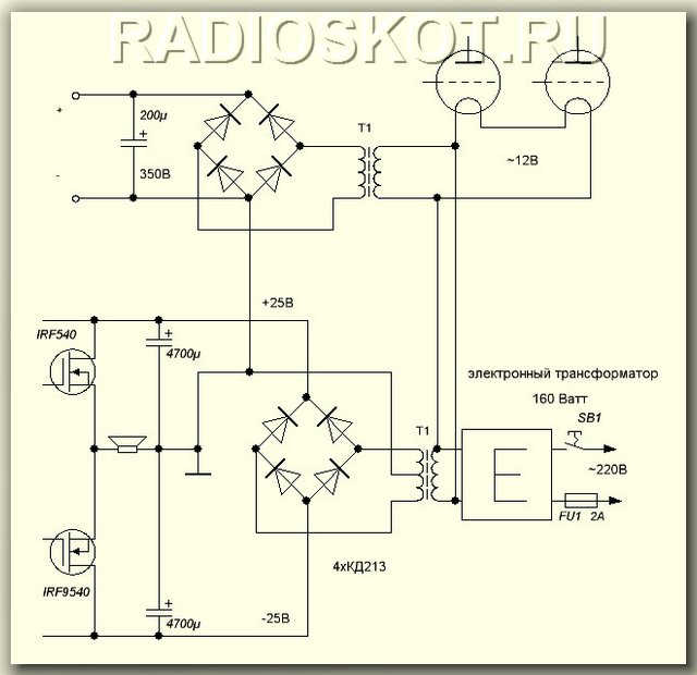
This hybrid amplifier circuit delivers 80 W of power into an eight-ohm load with a THD of 0.04%, a bandwidth of 5 Hz - 35 kHz (20 W, -3 dB) and a signal-to-noise ratio of over 100 dB.

The only voltage amplification stage in the circuit is built on a 2SC2547E bipolar transistor with a dynamic load on an ECC88 triode.
The output stage is designed as a push-pull source follower based on a complementary pair of powerful field-effect transistors IRF640, IRF9640. Their operating point is set by trimmer PR1 during adjustment.
Capacitor C2 and resistor R9 are used to form a voltage addition circuit familiar to transistor amplifiers. IN this diagram it helps radio tube V1 to ensure normal swing of the output stage at a relatively low anode voltage.
The audio signal, through the volume control on resistor R1, enters the VL1.1 triode (control grid) of the amplifier and is amplified. The negative bias potential slightly blocks the triode formed on its control grid with the help of the anode current, which passes through resistors R3 and R4 located in the cathode circuit. The voltage will drop across these resistances, therefore, relative to the negative bus, a positive voltage of approximately +1.7V will be present at the cathode of the lamp.

On the control grid of the amplifier tube, if compared with the cathode, there will be a negative bias potential, since the grid has a common contact through resistor R1 with ground. To reduce the effect of feedback, the tube amplifier circuit has a resistance R3, which is shunted by the electrolytic capacitance C1. Resistor R2 plays an important role as a load for the anode circuit of a tube amplifier. The voltage of the amplified audio signal generated on it is supplied through the isolation capacitor C2 to the control grid of the lamp pentode. Through the first output transformer, the signal amplified by it goes to the amplifier's loudspeaker.
Resistor R8 and capacitor C7 perform the same function as similar elements in the first stage. C6 and R6 are designed to change the timbre of the sound. Using resistor R9, a second negative circuit is obtained feedback. By capturing both stages of a tube amplifier, it reduces nonlinear distortion and creates the smoothest amplification of the audio signal across the entire audio frequency range.
The second transformer of the tube amplifier is wound on a magnetic core with a cross-section of 10 cm (W22 x 40). Primary winding- wire PEV-1 0.2-0.25 mm 1040 turns. The secondary winding has 965 turns of the same wire, the third has 34 turns wound with PEV-1 wire 0.6-0.8 mm.
The first transformer of the TVZ21 type. It is allowed to use any output transformer from a tube TV.

