12.09.2023
Low battery indicator. Simple Li-ion battery discharge indicator Do-it-yourself battery discharge indicator
Reader Maxim recently sent Li-ion batteries of the 18650 format, warning that they do not like deep discharge, as well as overcharging (for me, a transformer-network soul, such things are new). Okay, the charging issue is almost resolved - Uncle Liao promised to send the modules to TP4056. And you can figure out low voltage control yourself, for example, by using a dual comparator LM393.
A little theory. The 18650 lithium-ion battery is called so because of its dimensions: diameter 18 mm, length 65 mm. Like any Li-ion, it does not have a “memory effect”, does not tolerate complete discharge (it is better not to discharge below 3 volts) and can explode if charged incorrectly. There are models with built-in protection that turns off the battery when deep discharge and after charging is complete, but this does not apply to mine.

A fully charged battery produces 4.2 volts. By connecting them in series, we get 8.4 volts, which is quite enough for the Speedola 242 to work in the fresh air with almost no interference and no cartoon background at all, and even with backlighting. To prevent the “crocodiles” from accidentally closing during storage, I bite them on an ear stick or toothpick. A metal eye peeks out from under the electrical tape—the connection point between the two “cans.”

Operating principle. Measured voltage from the divider R1, R2 goes to the inverting inputs of the comparators In-1,In-2(it is half the input), and the reference (3.3 volts) is used for direct inputs In+1, In+2.
Let's say the battery is fully charged (8.4 volts). Then on the second and sixth legs of the microcircuit there are 4.2 volts, which is more than 3.3. Red LED VD2 not turned on, green light VD3. The voltage is normal.

The battery was discharged to 7 volts. The measured voltage is 3.5 volts, still higher than 3.3, and the green light is still on.

The battery was discharged to 6.4 volts. The measured voltage is 3.2 volts, which is less than 3.3. The red LED turns on and the green LED goes off. It's time to charge.
Travel notes:
— to save money, the indicator turns on “on demand” via a clock button;
— during prolonged operation, the left side of the circuit (resistors and zener diode) heats up more than we would like;
- by using R3 you can slightly change the operating limits of the comparator: for example, at 750 Ohms it was exactly 6 volts, and when connected in parallel to them 1.5 kOhm (total resistance 500 Ohms) became 6.4 volts;
- choosing a zener diode VD1 and resistor R3, you can monitor the discharge of batteries at a different voltage;

- if you want to plant VD3 cathode to ground (for example, in the case of a two-color LED), then you need to connect R5 and anode VD3 to the seventh leg of the microcircuit, and In+2 And In-2 swap;
— if indication of normal voltage is not needed, then all elements and connections to the second comparator (legs 5 -7) can be removed.
I didn’t gut my battery and immediately solder the indicator - maybe not the last one, but I’m sorry for the electrical tape.


For the future, there are modular holders on sale that can be used to easily assemble an unlimited number of batteries.
But a proven scheme will always do.
Update from 09.15.16

Likewise, an old laptop battery will do, and you can give it a second chance (even with simpler electronics, such as a radio). I did not separate the double “banks”, so their serial connection turned out to be quite long. Left and right - charging modules for TP4056.
How tightly Li-ion batteries have entered our lives. The fact that they are used in almost all microprocessor electronics is already the norm. So radio amateurs have long adopted them and use them in their homemade products. I contribute to this significant advantages Li-ion batteries, such as small size, large capacity, large selection executions of various capacities and forms.
The most common battery is 18650, its voltage is 3.7 V. For which I will make a discharge indicator.
It’s probably not worth telling how low discharge is harmful to batteries. And for batteries of all types. Correct operation rechargeable batteries will extend their life several times and save your money.
Charging indicator circuit

The circuit is quite universal and can operate in the range of 3-15 volts. The response threshold can be adjusted using a variable resistor. So the device can be used for almost any battery, be it acid, nickel-cadmium (nicd) or lithium-ion (Li-ion).
The circuit monitors the voltage and as soon as it drops below a predetermined level, the LED will light up, indicating low battery discharge.
The circuit uses an adjustable one (link where I got it). In general, this zener diode is a very interesting radio element, which can significantly make life easier for radio amateurs when constructing circuits related to stabilization or threshold operation. So take it into service, especially when building power supplies, current stabilization circuits, etc.
The transistor can be replaced with any other NPN structure, the domestic analogue of KT315, KT3102.
R2- adjusts the brightness of the LED.
R1 is a variable resistor with a nominal value of 50 to 150 kOhm.
The value of R3 can be increased to 20-30 kOhm to save energy if a high gain transistor is used.
If you don't have adjustable stabilizer TL431, then you can use a proven Soviet circuit with two transistors.

The response threshold is set by resistors R2, R3. Instead, you can solder one variable to allow adjustment and reduce the number of elements. Soviet transistors can be replaced with BC237, BC238, BC317 (KT3102) and BC556, BC557 (KT3107).

The circuit can be assembled on a board or mounted. Put on the heat shrink tube and blow it with a hot air gun. Attach with double-sided tape to the back of the case. I personally installed this board in a screwdriver and now I don’t drive its batteries until they are critically discharged.
You can also connect a buzzer (sweeter) in parallel with the resistor with the LED, and then you will know exactly about the critical thresholds.
TL431- a three-legged microcircuit, which is often called a “controlled zener diode”, because with its help you can obtain any voltage in the range of 2.5...36 volts. In addition, it can be used as a 2.5 volt comparator:
- if the input is less than 2.5 volts, no current flows through the output transistor of the microcircuit;
- if there is more than 2.5 volts at the input, the transistor is open and current flows through it.


It looks a lot like a transistor in switch mode, doesn’t it? And even the load - the same indicator LEDs - can be turned on in the same way as in a transistor switch.

Ready scheme for 7 volts(for two Li-ion batteries connected in series, where 8.4 volts when fully charged); to improve accuracy R2 can be made from a permanent 47k and tuning on 10k. Conclusion 1, drawing an analogy with n-p-n transistor - “base”, pin 2 – “emitter”, pin 3 – “collector” (conditionally, of course, a zener diode is not a transistor). As long as the voltage at the “base” is higher than 2.5 volts, the microcircuit is open and current flows through it. As the battery discharges, the voltage decreases, and as soon as less than 2.5 volts flows from the divider, the transistor of the microcircuit will close and current will flow through the LED.
If desired, you can assemble the same circuit using resistors 10k And 5k6- it will work, but will become a little more gluttonous. So, to save money, it is better to take larger resistors. I repeat: discharge indicator the battery shouldn't be too strong discharge.
R3 sets the current through the LED load and the output transistor of the microcircuit. It is selected at least according to the desired brightness of the glow.

Red LEDs require a low voltage to turn on (starting from 1.5 V), so they can glow even when TL431, in theory, is open and shunts them. The solution is to put a second LED or diode in series 1N4007. Or use LEDs with more high voltage inclusions - green, blue, white.
Progress is moving forward, and lithium batteries are increasingly replacing the traditionally used NiCd (nickel-cadmium) and NiMh (nickel-metal hydride) batteries.
With a comparable weight per element, lithium has large capacity, in addition, their element voltage is three times higher - 3.6 V per element, instead of 1.2 V.
The cost of lithium batteries has begun to approach that of conventional alkaline batteries, their weight and size are much smaller, and besides, they can and should be charged. The manufacturer says they can withstand 300-600 cycles.
There are different sizes and choosing the right one is not difficult.
The self-discharge is so low that they sit for years and remain charged, i.e. The device remains operational when needed.
"C" stands for Capacity
A designation like “xC” is often found. This is simply a convenient designation of the charge or discharge current of the battery with shares of its capacity. Derived from English word"Capacity" (capacity, capacity).When they talk about charging with a current of 2C, or 0.1C, they usually mean that the current should be (2 × battery capacity)/h or (0.1 × battery capacity)/h, respectively.
For example, a battery with a capacity of 720 mAh, for which the charge current is 0.5 C, must be charged with a current of 0.5 × 720 mAh / h = 360 mA, this also applies to discharge.
You can make a simple or not very simple charger yourself, depending on your experience and capabilities.
Circuit diagram of a simple LM317 charger

Rice. 5.
The application circuit provides fairly accurate voltage stabilization, which is set by potentiometer R2.
Current stabilization is not as critical as voltage stabilization, so it is enough to stabilize the current using a shunt resistor Rx and an NPN transistor (VT1).
The required charging current for a particular lithium-ion (Li-Ion) and lithium-polymer (Li-Pol) battery is selected by changing the Rx resistance.
The resistance Rx approximately corresponds to the following ratio: 0.95/Imax.
The value of resistor Rx indicated in the diagram corresponds to a current of 200 mA, this is an approximate value, it also depends on the transistor.
It is necessary to provide a radiator depending on the charging current and input voltage.
The input voltage must be at least 3 volts higher than the battery voltage to normal operation stabilizer, which for one can is? 7-9 V.
Circuit diagram of a simple charger on LTC4054

Rice. 6.
You can unsolder the LTC4054 charge controller from the old one cell phone, for example, Samsung (C100, C110, X100, E700, E800, E820, P100, P510).

Rice. 7. This small 5-legged chip is labeled "LTH7" or "LTADY"
Go into the smallest details I won’t work with the microcircuit, everything is in the datasheet. I will describe only the most necessary features.
Charge current up to 800 mA.
The optimal supply voltage is from 4.3 to 6 Volts.
Charge indication.
Output short circuit protection.
Overheating protection (reduction of charge current at temperatures above 120°).
Does not charge the battery when its voltage is below 2.9 V.
The charge current is set by a resistor between the fifth terminal of the microcircuit and ground according to the formula
I=1000/R,
where I is the charge current in Amperes, R is the resistor resistance in Ohms.
Lithium battery low indicator
Here simple circuit, which lights up the LED when the battery is low and its residual voltage is close to critical.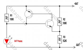
Rice. 8.
Any low-power transistors. The LED ignition voltage is selected by a divider from resistors R2 and R3. It is better to connect the circuit after the protection unit so that the LED does not drain the battery completely.
The nuance of durability
The manufacturer usually claims 300 cycles, but if you charge lithium just 0.1 Volt less, to 4.10 V, then the number of cycles increases to 600 or even more.Operation and Precautions
It's safe to say that lithium polymer batteries the most “delicate” batteries in existence, that is, they require mandatory compliance with several simple but mandatory rules, failure to comply with which can lead to troubles.1. Charge to a voltage exceeding 4.20 Volts per jar is not allowed.
2. Not allowed short circuit battery
3. Discharge with currents exceeding load capacity or heating the battery above 60°C. 4. A discharge below a voltage of 3.00 Volts per jar is harmful.
5. Heating the battery above 60°C is harmful. 6. Depressurization of the battery is harmful.
7. Storage in a discharged state is harmful.
Failure to comply with the first three points leads to a fire, the rest - to complete or partial loss of capacity.
From the practice of many years of use, I can say that the battery capacity changes little, but increases internal resistance and the battery begins to work less time at high current consumption - it seems that the capacity has dropped.
For this reason, I usually install a larger container, as the dimensions of the device allow, and even old cans that are ten years old work quite well.
For not so much high currents Use old cell phone batteries.

You can get a lot of perfectly working 18650 batteries out of an old laptop battery.
Where do I use lithium batteries?
I converted my screwdriver and electric screwdriver to lithium a long time ago. I don't use these tools regularly. Now, even after a year of non-use, they work without recharging!I put small batteries in children's toys, watches, etc., where 2-3 “button” cells were installed from the factory. Where exactly 3V is needed, I add one diode in series and it works just right.
I put them in LED flashlights.
Instead of the expensive and low-capacity Krona 9V, I installed 2 cans in the tester and forgot all the problems and extra costs.
In general, I put it wherever I can, instead of batteries.
Where do I buy lithium and related utilities
For sale. At the same link you will find charging modules and other useful items for DIYers.The Chinese usually lie about the capacity and it is smaller than what is written.

Honest Sanyo 18650
A battery charge indicator is a necessary thing in the household of any motorist. The relevance of such a device increases many times over when, for some reason, a car refuses to start on a cold winter morning. In this situation, it’s worth deciding whether to call a friend to come and help you start from your battery, or whether the battery has died for a long time, having discharged below a critical level.
Why monitor your battery's condition?
A car battery consists of six batteries connected in series with a supply voltage of 2.1 - 2.16V. Normally, the battery should produce 13 - 13.5V. Significant discharge should not be allowed battery, since in this case the density decreases and, accordingly, the freezing temperature of the electrolyte increases.
The higher the battery wear, the less time it holds a charge. In the warm season this is not critical, but in winter they are forgotten when turned on side lights by the time they return, they can completely “kill” the battery, turning the contents into a piece of ice.
In the table you can see the freezing temperature of the electrolyte, depending on the degree of charge of the unit.
| Dependence of the freezing temperature of the electrolyte on the state of charge of the battery | ||||
|---|---|---|---|---|
| Electrolyte density, mg/cm. cube | Voltage, V (no load) | Voltage, V (with load 100 A) | Battery charge level, % | Electrolyte freezing temperature, gr. Celsius |
| 1110 | 11,7 | 8,4 | 0,0 | -7 |
| 1130 | 11,8 | 8,7 | 10,0 | -9 |
| 1140 | 11,9 | 8,8 | 20,0 | -11 |
| 1150 | 11,9 | 9,0 | 25,0 | -13 |
| 1160 | 12,0 | 9,1 | 30,0 | -14 |
| 1180 | 12,1 | 9,5 | 45,0 | -18 |
| 1190 | 12,2 | 9,6 | 50,0 | -24 |
| 1210 | 12,3 | 9,9 | 60,0 | -32 |
| 1220 | 12,4 | 10,1 | 70,0 | -37 |
| 1230 | 12,4 | 10,2 | 75,0 | -42 |
| 1240 | 12,5 | 10,3 | 80,0 | -46 |
| 1270 | 12,7 | 10,8 | 100,0 | -60 |
A drop in charge level below 70% is considered critical. All automotive electrical appliances consume current, not voltage. Without load, even a severely discharged battery can show normal voltage. But at a low level, during engine startup, a strong voltage drop will be noted, which is an alarming signal.
It is possible to notice an approaching disaster in a timely manner only if an indicator is installed directly in the cabin. If, while the car is running, it constantly signals about discharge, it’s time to go to the service station.
What indicators exist
 Many batteries, especially maintenance-free ones, have a built-in sensor (hygrometer), the operating principle of which is based on measuring the density of the electrolyte.
This sensor monitors the condition of the electrolyte and the relative value of its indicators. It is not very convenient to climb under the hood of a car several times to check the condition of the electrolyte in different operating modes.

Electronic devices are much more convenient for monitoring the condition of the battery.
Types of battery charge indicators
Automotive stores sell many of these devices, differing in design and functionality. Factory devices are conventionally divided into several types.
By connection method:
- to the cigarette lighter socket;
- to the on-board network.
By signal display method:
- analog;
- digital.

The principle of operation is the same, determining the battery charge level and displaying information in a visual form.
 Schematic diagram indicator
 How to make a battery charge indicator using LEDs?
There are dozens of different control schemes, but they produce identical results. It is possible to assemble such a device yourself from scrap materials. The choice of circuit and components depends solely on your capabilities, imagination and the assortment of the nearest radio store.
Here is a diagram to understand how the LED battery charge indicator works. This portable model can be assembled “on your knee” in a few minutes.

D809– a 9V zener diode limits the voltage on the LEDs, and the differentiator itself is assembled on three resistors. Such LED indicator triggered by current in the circuit. At a voltage of 14V and above, the current is sufficient to light up all the LEDs; at a voltage of 12-13.5V they light up VD2 And VD3, below 12V - VD1.
A more advanced option with a minimum of parts can be assembled using a budget voltage indicator - chip AN6884 (KA2284).
Scheme led indicator battery charge level on the voltage comparator

The circuit operates on the principle of a comparator. VD1– a 7.6V zener diode, it serves as a reference voltage source. R1– voltage divider. During the initial setup, it is set to such a position that all LEDs light up at a voltage of 14V. The voltage supplied to inputs 8 and 9 is compared through a comparator, and the result is decoded into 5 levels, lighting the corresponding LEDs.
Battery charging controller
To monitor the battery status during operation charger, we make a battery charge controller. The device circuit and components used are as accessible as possible, while at the same time providing complete control over the battery recharging process.
The principle of operation of the controller is as follows: while the voltage on the battery is below the charging voltage, the green LED lights up. As soon as the voltage is equal, the transistor opens, lighting up the red LED. Changing the resistor in front of the base of the transistor changes the voltage level required to turn on the transistor.
This universal scheme control that can be used for both powerful car batteries, and for miniature lithium batteries.

